GBS Elektronik MCA-527 Firmware Commands User Manual
Page 36
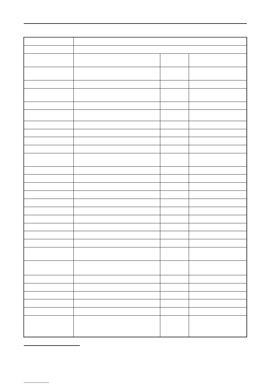
MCA527
Command name
CMD_QUERY_STATE527 (1
st
Continuation)
Result data array
Byte offset 58
Power module firmware version
unsigned char High nibble: major version
Low nibble:
minor version
Byte offset 59
Power module hardware version
unsigned char High nibble: major version
Low nibble:
minor version
Byte offset 60
Power module serial number
unsigned short
Byte offset 62
Power module ID
unsigned short Full version
= 0
Lite version
= 1
Byte offset 64
Maximum allowed high voltage
unsigned short
Byte offset 66
Threshold [ * 0.1 %]
unsigned short
See CMD_QUERY_STATE and
CMD_SET_THRESHOLD_TENTHS
Byte offset 68
Fast dead time [msec]
unsigned long
Byte offset 72
Evaluation filter type
unsigned short
Byte offset 74
Flattop time [ * 0.1 µsec]
unsigned short
See CMD_SET_FLAT_TOP_TIME
Byte offset 76
Evaluation filter size
unsigned short
Byte offset 78
Trigger level for automatic threshold calculation
[ * 0.0625]
unsigned short 80 … 1600
Byte offset 80
MCA temperature [ * 0.0078125 °C] at stop
short
0x8000 = not available
Byte offset 82
Detector temperature [ * 0.0078125 °C] at stop
short
0x8000 = not available
Byte offset 84
Customized IP address
unsigned char [4]
See CMD_SET_IP_ADDRESS
Byte offset 88
Actual IP address
unsigned char [4]
Byte offset 92
MCS time per channel [ *
0.1 msec]
unsigned long
Byte offset 96
Elapsed time per channel [ * 0.1 msec]
unsigned long
Byte offset 100
Auto trigger threshold [ * 0.00006103515625]
long
Byte offset 104
Power module temp. [ * 0.0078125 °C] at stop
short
0x8000 = not available
Byte offset 106
Command flag and parameters
8 bytes
Byte offset 114
Jitter correction
unsigned char 0 = off, 1 = on
Byte offset 115
Baseline restoring
unsigned char 0 = off, 1 = 1/1, 2 = 1/2, 3 = 1/4,
4 = 1/8, 5 = 1/16, 6 = 1/32
Byte offset 116
Set trigger threshold [ * 0.00006103515625]
long
0 … 268435455
0 = auto threshold calculation
Byte offset 120
Input mode
unsigned char 0 = alterable, 1 = fixed
Byte offset 121
Highest allowed shaping time [ * 0.1 µsec]
unsigned char
Byte offset 122
Gating mode
unsigned char See CMD_SET_GATING
Byte offset 123
Gating signal
unsigned char See CMD_SET_GATING
Byte offset 124
Gating shift
unsigned char See CMD_SET_GATING
Byte offset 125
Hardware-based coarse gain levels
(All other coarse gain levels are realized by the
firmware.)
unsigned char Bit 0: 2, Bit 1: 5, Bit 2: 10,
Bit 3: 20, Bit 4: 50, Bit 5: 100
Bit 6: 200, Bit 7: 500
37 The maximum allowed high voltage is determined by the power module, and in some system configurations if the detector is
firmly connected, additionally by the maximum high voltage of the detector.
38 Since firmware version 13.05.
36