Battery installation, Battery removal, Battery testing – NavCom SF-2040 Rev.F User Manual
Page 41: Figure 6: battery locking clips
SF-2040 User Guide – Rev. F
Battery Installation
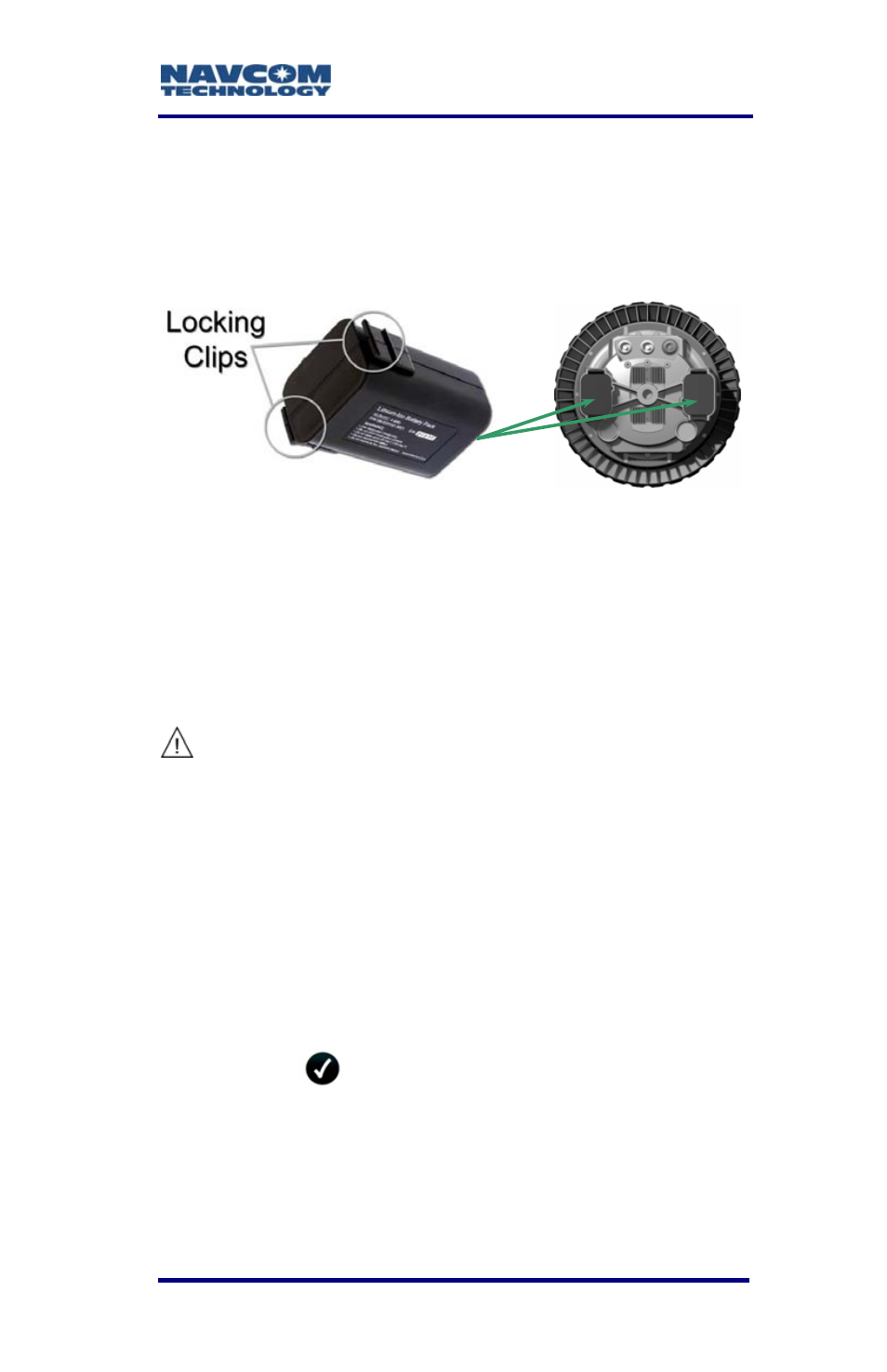
The battery packs are keyed to prevent improper
installation. There are two locking clips on either side
of the battery end (see Figure 6).
Figure 6: Battery Locking Clips
The bottom of the sensor has two battery chambers.
Install each battery pack by sliding it into a chamber.
Align the channel on the chamber to match the
battery notch. Press the end firmly until the locking
clips click. Verify both locking clips are locked in
place.
If both locking clips are not locked in
place, a battery pack could
inadvertently drop to the ground.
Battery Removal
Using the thumb and the middle finger, depress the
two locking clips firmly. The battery pack should pop
out enough to be pulled free of the chamber.
Battery Testing
Depress the
button on the indicator panel to
check the status of the battery charge. Refer to
Table 5 for battery status LED indications.
3-39