Communication port connectivity, Figure 8: sf-2040 block diagram – NavCom SF-2040 Rev.F User Manual
Page 46
SF-2040 User Guide – Rev. F
3-44
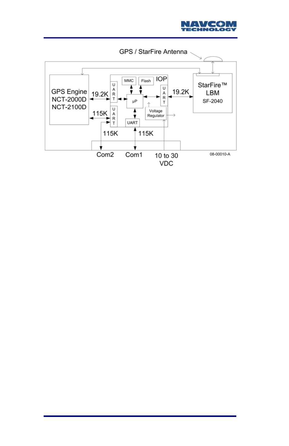
Figure 8: SF-2040 Block Diagram
Communication Port Connectivity
Connect the supplied LEMO 7-Pin connector of the
serial cable (P/N 94-310090-3003) to COM 2 (factory
default Control Port) of the SF-2040. Connect the
DB9S end to the control device.
Some devices may require an additional
adaptor, as the receiver is configured as a
DCE device.
COM 2 is the SF-2040 logical control port by
default. COM 1 can be configured as the
control port by using the appropriate NavCom
proprietary commands or StarUtil. However,
there are caveats to Logical / Physical port
assignments.
The Control Port is a logical input/output port
and can not share the physical port with any
other logical port. The Control Port typically
handles the most data and requires baud
rates in excess of 19.2K baud, particularly in
multi-hertz measurement and navigation