Wiring, Modgas-x field technical guide 10, Warning – Orion System MODGAS-X User Manual
Page 10
WIRING
MODGAS-X Field Technical Guide
10
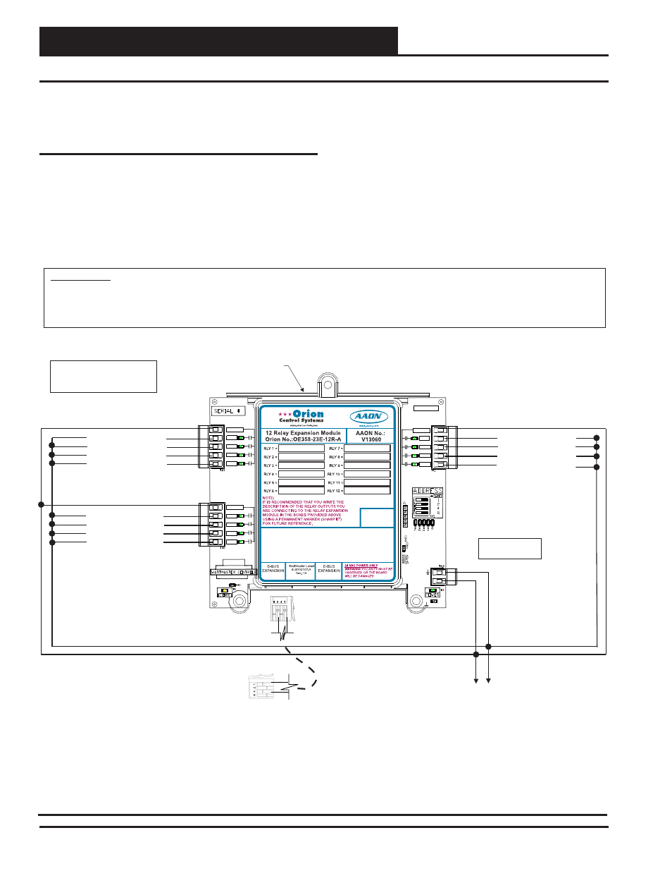
Two Modulating Valves & Up To 13 Stages Fixed Heat - Stand-Alone
Two Modulating Valve With Up To 13
Additional Stages Of Fixed Heat
Stand-Alone Wiring, Continued
If communication is lost to the 12-Relay E-BUS Expansion Module,
the 12-Relay E-BUS Expansion Module will turn off its relays and
the MODGAS-X Controller will alarm and fall back to using only
its onboard stages. If communications is restored, the MODGAS-X
Controller will begin staging up if needed.
Figure 7: Two Modulating Valves & 13 Stages of Fixed Heat - 12-Relay E-BUS Expansion Module
12-Relay E-BUS
Expansion Module
RLY9
R1
R5
RLY10
R2
R6
RLY11
R3
R7
RLY12
R4
R8
EBC E-BUS Cable
Connect To MODGAS-X Controller
24 VAC
GND
15 VA Minimum
Power Required
WARNING!!
Observe Polarity! All boards must be wired with GND-to-GND and 24VAC-to-24VAC. Failure to observe polarity will result in damage to
one or more of the boards. Expansion Modules must be wired in such a way that the expansion modules and the controller are always
powered together. Loss of power to the expansion module will cause the controller to become inoperative until power is restored to the
expansion module.
Note:
All Relay Outputs Are Normally Open
And Rated For 24 VAC Power Only.
1 Amp Maximum Load.
RLY9
RLY10
RLY11
RLY12
RLY-COM
MADE IN USA
RLY-COM
RLY-COM
RLY1
RLY2
RLY3
RLY4
RLY8
RLY7
RLY6
RLY5
24VAC
GND
EXPANSION BOARD
YS102324 REV 2
RELAY
24 V
A
C
GND
RLY1
RLY2
RLY3
RLY4
COM
COM
RLY5
RLY6
RLY7
RLY8
COM
Heat Stage 4 (Fixed)
Heat Stage 5 (Fixed)
Heat Stage 6 (Fixed)
Heat Stage 7 (Fixed)
Heat Stage 8 (Fixed)
Heat Stage 9 (Fixed)
Heat Stage 10 (Fixed)
Heat Stage 11 (Fixed)
Heat Stage 12 (Fixed)
Heat Stage 13 (Fixed)
Heat Stage 14 (Fixed)
Heat Stage 15 (Fixed)
R9
R10
R11
R12
Revised 9/30/14