Wiring, Two modulating staged valves - stand-alone wiring, Modgas-x field technical guide – Orion System MODGAS-X User Manual
Page 11: Two modulating staged valves wiring
MODGAS-X Field Technical Guide
WIRING
11
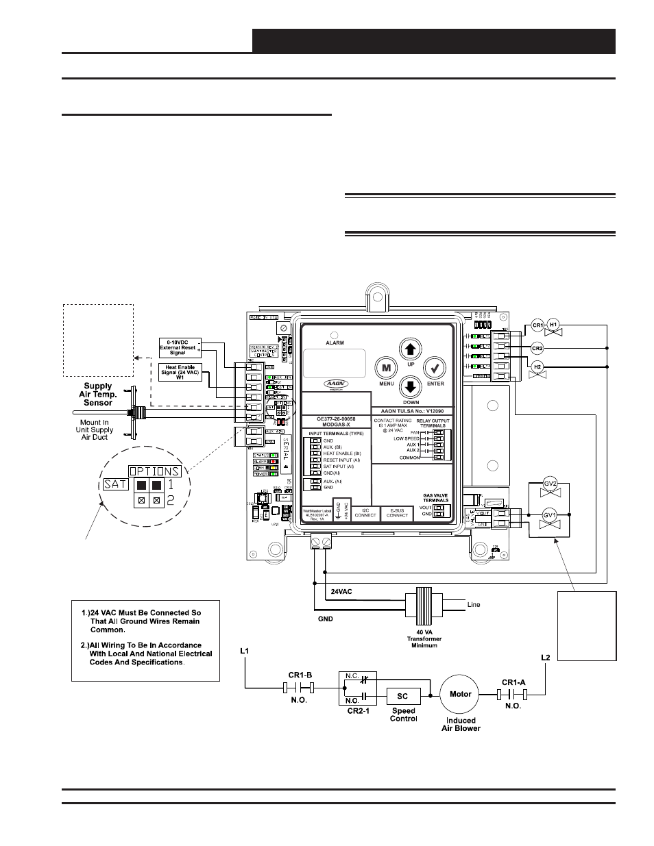
Two Modulating Staged Valves - Stand-Alone Wiring
MODGAS-X CONTROLLER
(OE377-26-00058)
Low Speed Fan
See
For
Settings.
Only One Supply Air Temperature Sensor
Can Be Used Per Application.
Table 8, Page 24
SAT OPTIONS Jumper
24 VAC Power
Input Terminals
Max. Power
Consumption
1 Gas Valve
= 18 VA
2 Gas Valves
= 33 VA
Stage 2 Heat (Mod)
Fan Enable and
Stage 1 Heat (Mod)
Connect SAT and
Input to
Board’s
Input If
Applicable.
See
.
GND
Reheat
SAT
Table 7,
Page 24
Figure 8: Two Modulating Staged Valves Stand-Alone Wiring Diagram
Two Modulating Staged Valves Wiring
In this confi guration, the fi rst Modulating Valve is enabled by the
FAN RLY. The second Modulating Valve is enabled by the AUX1
relay.
This confi guration operates as Stand-Alone (Figure 8, below) or
communicating with an AAON Unit Controller (Figure 9, page 12).
If using a MHGRV-X Controller along with the MODGAS-X
Controller in Stand-Alone, the SAT Sensor always connects to the
MODGAS-X Controller.
This confi guration
can use either the MAXITROL
®
0-20 volt valve(s)
or the MAXITROL
®
EXA STAR 0-10 volt stepper valve(s)—confi g-
ured at the factory.
See Appendix C, page 26 for depiction.
WARNING: Do Not Connect Power To VOUT/Ground
Terminal
Block!