Troubleshooting, Alarms & led locations, Modgas-x field technical guide 20 – Orion System MODGAS-X User Manual
Page 20
TROUBLESHOOTING
MODGAS-X Field Technical Guide
20
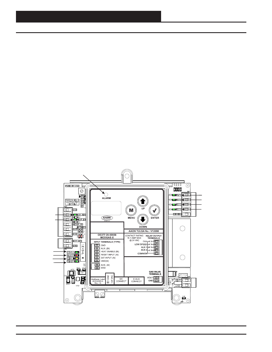
Figure 11: MODGAS-X Controller LED Locations and Descriptions
FAN LED
LOW SPEED FAN LED
AUXILIARY HEAT LED
NOT USED
NOT USED
ALARM LED
COMM LED
POWER LED
HEAT ENABLE LED
STATUS LED
ALARM LED
MODGAS-X CONTROLLER
(OE377-26-00058)
Supply Air Temperature Failure:
•
Verify that the Supply Air Temperature Sensor is
connected to the SAT and GND on the MODGAS-X
(stand-alone mode or when using Retrofi t
Applications.
See
Table 7, page 24.) or to AI2 and
GND on specifi c Main Controllers (communicating
mode).
See
Table 7, page 24.
•
Remove SAT and GND wiring from MODGAS-X
and ohm the sensor out (this may indicate open or
failed wiring). Refer to chart in back of this guide for
readings.
•
Verify the SAT OPTIONS jumper settings on the
MODGAS-X for the Supply Air Temperature Sensor.
Sat Cutoff Mode:
•
Remove SAT and GND wiring from the MODGAS-X
and ohm the sensor out (this may indicate open or
failed wiring). Refer to chart in back of guide for
readings.
Alarms & LED Locations
•
With Supply Air Sensor disconnected from the
MODGAS-X, set volt meter to DC volts and measure
voltage between SAT and GND on board. Refer to
Tables 5 & 6, pages 21 & 22 for readings.
•
Verify Supply Air Temperature Sensor reading in duct
with 3rd party temperature testing device.
Communications Loss:
•
Check COMM LED on MODGAS-X.
•
Verify 24 VAC power to all interconnected
WattMaster
controllers.
•
Verify connection between the MODGAS-X
and associated WattMaster controllers.
•
In communication mode (connected to a an AAON
Unit with modular cable), confi rm that Unit
Controller’s MODGAS-X status screen displays
MODGAS-X’s Supply Air Temperature and that Main
MODGAS screens show COMM MODE.