Inputs & outputs, Inputs and outputs – Orion System MODGAS-X User Manual
Page 13
MODGAS-X Field Technical Guide
INPUTS & OUTPUTS
13
Inputs and Outputs
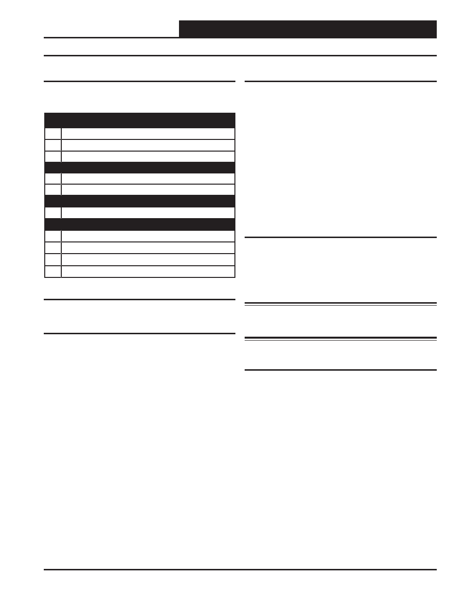
Table 1: MODGAS-X Controller Inputs & Outputs
Analog Inputs
Reset Input (RST IN)
Used only in stand-alone operation. The Discharge Temperature
Setpoint can be reset by supplying a 0-10 VDC signal to the RST
IN low voltage terminal block. This reset signal is optional and need
only be used if you require resetting of the discharge air temperature.
Supply Air Temperature Sensor (SAT)
Used in stand-alone operation and when MODGAS-X is connected
to a CAV/VAV or MUA Controller. The Supply Air Temperature
Sensor is the control source. This sensor has to be installed for the
unit to operate. The Supply Air Sensor is located in the discharge
air stream and monitors discharge air temperature to maintain the
discharge air temperature setpoint.
I/O Map
See Table 1 below to reference the inputs and outputs that are avail-
able on the MODGAS-X Controller.
Analog Inputs
1
(RST IN) Reset Signal
2
(SAT) Supply Temperature
3
(AUX AI) Not Used
Binary Inputs
1
(AUX BI) Not Used
2
(HEAT EN) Heat Enable
Analog Output (0-20 or 0-10 VDC)
1
(VOUT) Heat Valve
Relays
1
(FAN) Fan and Stage 1 Heat (Modulating)
2
(LOW SPEED) Low Speed Fan
3
(AUX 1) Stage 2 Heat (Fixed or Modulating)
4
(AUX 2) Stage 3 Heat (Fixed or Modulating)
Binary Inputs
Heat Enable Contact (HEAT EN)
This input is only required when the controller is used in stand-alone
operation; it is not required when communicating with an AAON
Unit Controller. The Heat Enable input is activated by a 24VAC
signal supplied from a building automation system to enable the
MODGAS-X Controller. The controller will not operate without
24VAC being applied to this input terminal when used in a stand-
alone confi guration. When the Heat Enable signal is lost or turned
off, all stages de-activate immediately.
This enable input can be used in communication mode for special
circumstances. Heat enable can be activated by either communica-
tions or this enable input. Heat enable will be deactivated when both
signals from communications and the enable input is turned off.
Analog Output
Gas Valve Output (VOUT)
Depending on the type of valve used, this output will supply a 0-20
VDC or 0-10 VDC output signal for control of the modulating gas
valve. With a 0-20 VDC valve, the operation is reverse acting, so
high voltage means closed and low voltage means open. With a 0-10
VDC valve, the operation is direct acting.
WARNING: For 0-20 VDC valves, the maximum number
that can be connected/confi gured is 2. For 0-10 VDC valves,
the maximum number that can connected/confi gured is 4.
Relay Outputs
Relay #1 - Fan and Stage 1 Heat Modulating
When the MODGAS-X Controller has heat enabled, this relay closes
to bring the induced draft blower on at high speed. The controller
will activate the Low Speed Fan Relay to reduce the induced draft
blower speed as the gas valve modulates closed. This relay is also
used to enable Modulating Heat Valve 1.
Relay #2 - Low Speed Fan
Depending on the gas valve position, this relay will close to switch
the induced draft blower to low speed. The controller automatically
switches the blower to low speed as the gas valve modulates closed
in order to maintain the proper fuel to air ratio.
Revised 9/30/14