Wiring, Modgas-x field technical guide 6 – Orion System MODGAS-X User Manual
Page 6
WIRING
MODGAS-X Field Technical Guide
6
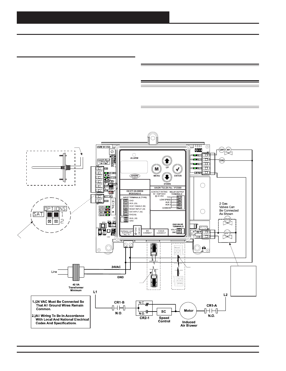
Single Modulating Valve No Staging - Communicating Wiring
Figure 3: Single Modulating Valve No Staging Communicating Wiring Diagram
MODGAS-X CONTROLLER
(OE377-26-00058)
Supply
Air Temperature
Sensor
Mount In Supply
Air Duct
Connect
o AI2 & GND
On Main Controller
(This Does Not Apply To
Retrofit Applications.
See
.)
Supply Air Temperature
Sensor T
Table 7, Page 24
EBC E-BUS Cable
Connects To
VCB-X Controller’s
Expansion
Port
Low Speed Fan
24 VAC Power
Input Terminals
Max. Power
Consumption
1 Gas Valve
= 18 VA
2 Gas Valves
= 33 VA
I C Cable
Connects To
I C Port On
Any Non VCB-X Controller
Or Expansion Module
2
2
Fan Enable And
Stage 1 Heat (Mod)
The SAT OPTIONS Jumper Setting
Should Be Set to 1.
See
For Settings.
Only One Supply Air Temperature Sensor
Can Be Used Per Application.
Table 9, Page 24
Single Modulating Valve No Staging -
Communicating Wiring
This confi guration operates as Stand-Alone (Figure 2, page 5) or
communicating with an AAON Unit Controller (Figure 3, below).
For connection to a VCB-X Controller or VCB-X Expansion Mod-
ule, use an E-BUS Cable connecting to the appropriate E-BUS ports
on those controllers. For all other controllers, including VAV/CAV,
MUA, VCM, VCM-X, SA, and RNE Controllers, use an I
2
C Cable
connecting to the appropriate I
2
C ports on those controllers.
This confi guration
can use either the MAXITROL
®
0-20 volt valve(s)
or the MAXITROL
®
EXA STAR 0-10 volt stepper valve(s)—confi g-
ured at the factory.
See Appendix C, page 26 for depiction.
WARNING: Do Not Connect Power To VOUT/Ground
Terminal
Block!
NOTE: If additional fi xed stages are required, these should be
confi gured and wired to the AAON Unit Controller’s
relays.