Wiring, Modgas-x field technical guide – Orion System MODGAS-X User Manual
Page 7
MODGAS-X Field Technical Guide
WIRING
7
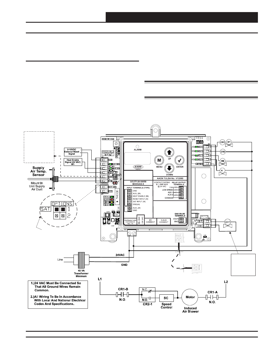
Single Modulating Valve & Up To 14 Stages Fixed Heat Stand-Alone
Figure 4: Single Modulating Valve - Stand-Alone
MODGAS-X CONTROLLER
(OE377-26-00058)
See
For
Settings.
Only One Supply Air Temperature Sensor
Can Be Used Per Application.
Table 8, Page 24
SAT OPTIONS Jumper
24 VAC Power
Input Terminals
Max. Power
Consumption
1 Gas Valve
= 18 VA
EBC-E-BUS Cable
Connects To
12 Relay E-BUS
Expansion
Port
Fan Enable And
Stage 1 Heat (Mod)
Low Speed Fan
Stage 2 Heat (Fixed)
Stage 3 Heat (Fixed)
3
Connect SAT and
Input to
Board’s
Input If
Applicable.
See
.
GND
Reheat
SAT
Table 7,
Page 24
One Modulating Valve With Up To 14
Additional Stages Of Fixed Heat
Stand-Alone Wiring
This confi guration only applies to a Stand-Alone operation (Figure
4, below) and is factory-confi gured.
If using a MHGRV-X Controller along with the MODGAS-X
Controller in Stand-Alone, the SAT Sensor always connects to the
MODGAS-X Controller.
The fi rst two fi xed stages use AUX1 and AUX2 relays to enable
them (Figure 4, below). Additional fi xed stages can be added by
using the 12-Relay E-BUS Expansion Module. (Figure 5, page 8).
This configuration
can use either the MAXITROL
®
0-20 volt
valve(s) or the MAXITROL
®
EXA STAR 0-10 volt stepper valve(s)
(confi gured at the factory).
See Appendix C, page 26 for depiction.
WARNING: Do Not Connect Power To VOUT/Ground
Terminal
Block!