2 – names and functions of parts, Rear panel – Teac DA-3000 User Manual
Page 13
TASCAM DA-3000
13
2 – Names and Functions of Parts
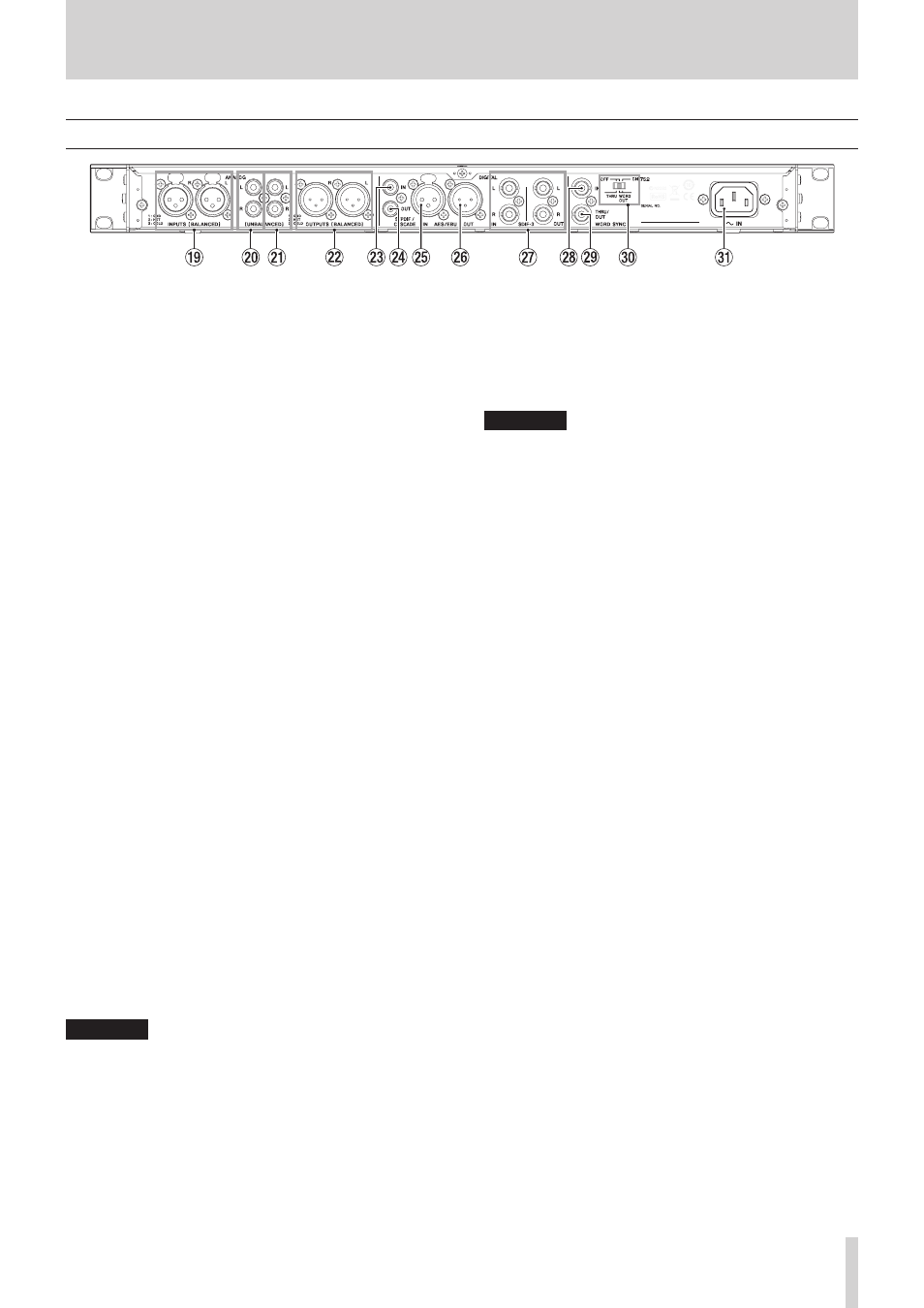
Rear panel
o
L/R ANALOG INPUTS (BALANCED)
These balanced analog XLR input connectors have a default
nominal input level of +4 dBu, but it can also be set to +6
dBu.
(1: GND, 2: HOT, 3: COLD)
(See “Setting the reference level” on page 25.)
p
L/R ANALOG INPUTS (UNBALANCED)
These analog RCA pin input jacks have a nominal input level
of −10 dBV.
a
L/R ANALOG OUTPUTS (UNBALANCED)
These analog RCA pin output jacks have a nominal output
level of −10 dBV.
s
L/R ANALOG OUTPUTS (BALANCED)
These balanced analog XLR output jacks have a nominal
output level of +4 dBu, but it can also be set to +6 dBu.
(1: GND, 2: HOT, 3: COLD)
(See “Setting the reference level” on page 25.)
d
DIGITAL IN(S/PDIF / CASCADE)
These are digital audio input connectors.
This digital input jack has a sampling rate converter that
supports 32 —192 kHz. (See “Using the sampling rate
converter” on page 23.)
When connecting this unit to cascade multiple units, connect
the DIGITAL OUT(S/PDIF / CASCADE) jack of another unit
to this jack. (See “Connections and preparations” on page
f
DIGITAL OUT(S/PDIF / CASCADE)
This digital output jack can output digital audio in
IEC60958-3 (S/PDIF) format.
To connect multiple DA-3000 units, connect the DIGITAL IN
(S/PDIF / CASCADE) jack of another unit to this jack. (See
“Connections and preparations” on page 42.)
g
DIGITAL IN (AES/EBU)
This balanced XLR digital audio input jack supports the input
of AES3-2003/IEC60958-4 (AES/EBU) format digital audio.
This digital input jack has a sampling rate converter that
supports 32 —192 kHz. (See “Setting the reference level” on
h
DIGITAL OUT (AES/EBU)
This balanced XLR digital audio output jack can output
digital audio in AES3-2003/IEC60958-4 (AES/EBU) format.
CAUTION
When the DIGITAL IN/OUT (SDIF-3) connectors are
connected, the DIGITAL IN/OUT (S/PDIF / CASCADE) and
DIGITAL IN/OUT (AES/EBU) connectors cannot be used to
input and output digital audio signals.
j
DIGITAL IN/OUT(SDIF-3) connectors
These are digital audio input and output connectors for DSD
signals.
These are digital audio input and output connectors for the
SDIF-3 (DSD-raw) format.
Each connector carries either the left or right channel of the
stereo signal.
CAUTION
When the DIGITAL IN/OUT (SDIF-3) connectors are
connected, all digital audio devices (including this unit) in
the system must be synchronized to the same clock source.
To sync this unit to an external clock, input a 44.1kHz clock
signal through its WORD SYNC IN connector.
If the clock master within the system is set to 44.1kHz, DSD
audio sources will become clock slaves. For details see,
“Setting the master clock” on page 25.
k
WORD SYNC IN connector
Use to input a word clock signal.
When syncing this unit to an external clock signal, the word
clock signal input through this connector is used.
l
WORD SYNC THRU/OUT connector
This is a BNC word clock through/output connector that can
output a word clock signal (thru or 44.1kHz, 48kHz, 88.2kHz,
96kHz, 176.4kHz or 192kH).
Use the THRU/WORD OUT switch to change between thru
and word output.
;
75Ω ON/OFF [THRU/WORD OUT] switch
Use to make the following settings.
o
Whether or not the WORD SYNC IN connector has
termination resistance (75 Ω)
o
WORD SYNC THRU/OUT connector THRU/OUT
setting
z
AC IN connector
Connect the included power cord here.