ARAG BRAVO130 User Manual
Page 13
13
8.1.4
Row distance
The
“ROW DISTANCE” function allows programming and recalling with a single key all the para-
meters relative to the distances between the rows of trees to be treated, so as to correctly calculate
the surface area treated and the volume of liquid sprayed in
liters/hectare.
Up to 5 types of rows can be programmed: to perform the setting, follow the procedure shown
below:
1) Scroll through the functions on the User menu using the
and
keys and select the
entry
“ROW DISTANCE”.
2) Confirm the selection by pressing the
key.
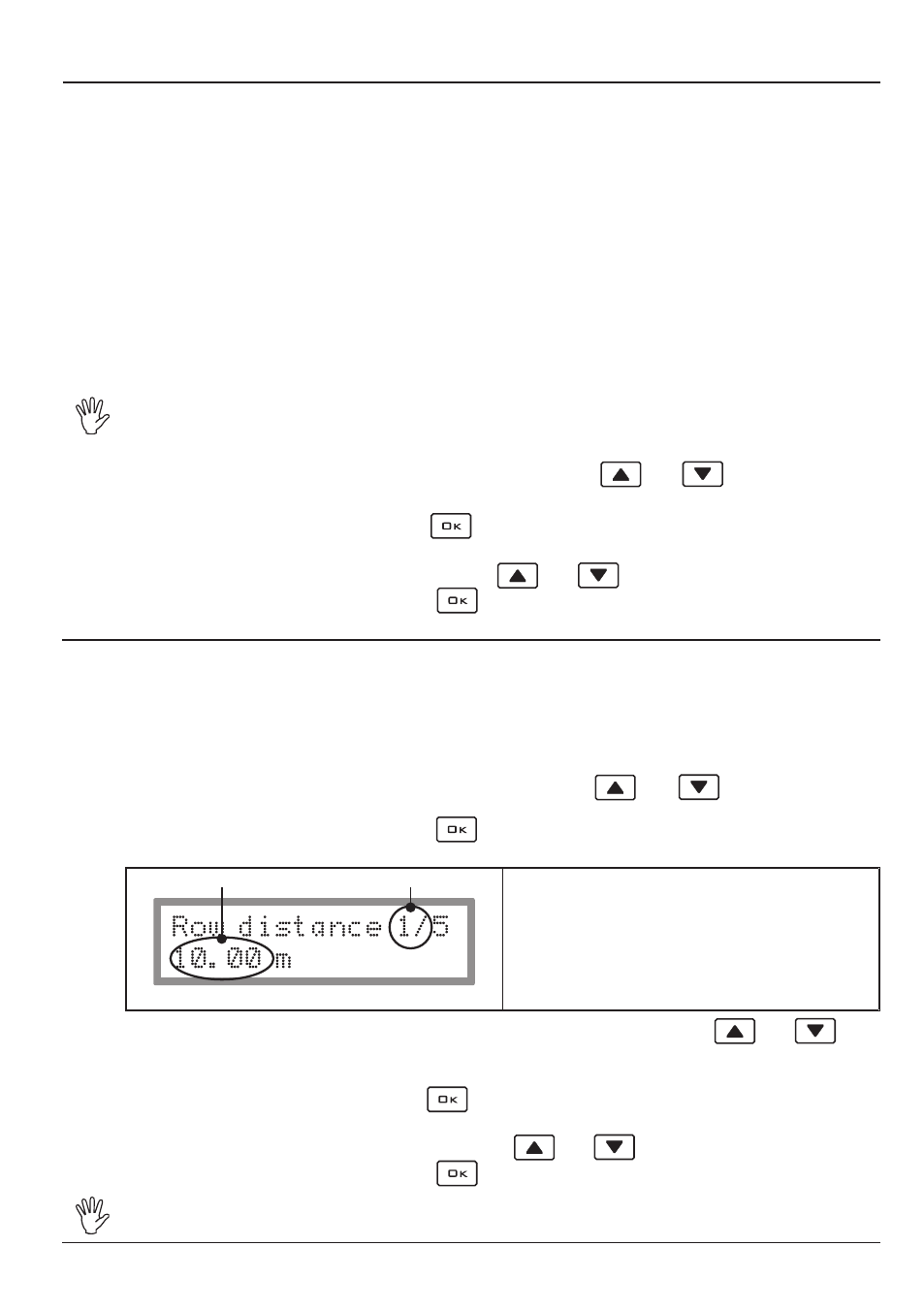
The following information will appear on the display:
A
B
Fig. 5
A • the type of row active, indicated by a number
from 1 to 5;
B • the value of the distance between rows.
3) Select the type of row you wish to set by scrolling to the
A
value using the
and
keys;
while scrolling, the display will show the distance between rows (
B
) corresponding to the type of
row activated.
4) Confirm the selection by pressing the
key: in this way, the number that indicates the distance
between rows (
B
) will flash on the display.
5) Change the value
B
on the display by using the
and
keys.
6) Confirm the value set by pressing the
key.
ARAG code 46713000.100 ultrasound sensors detect the presence of the plant up to
a distance of 6 m.
8.1.3
Product density
The quantity of the products sprayed can vary according to their density.
For this reason, the computer allows you to enter a density factor and, thus, to calculate the quantity
of liquid effectively sprayed.
This value is very important because, if mechanical palette or turbine flowmeters are used, since
these are affected by variations in the density of the liquid, it could happen that the liquid will be
sprayed in a different quantity than that set and measured by the computer.
The preset density factor is “1” and it refers to water or, at any rate, a liquid having the same
density as water.
Since it would be impossible to provide a table with density data for all products that can be sprayed,
it is up to the user to evaluate any correction to the entered value that will allow the computer the
possibility to exactly indicate the quantity dispensed:
- if, at the end of spraying, the tank still contains liquid, the density factor must be decreased;
- if, on the other hand, the liquid is finished before the end of distribution, the factor must be in-
creased.
An electromagnetic flowmeter such as the ORION series 462XXX is not affected by
the difference in liquid density: for this reason, if this flowmeter is present in your
system, set the density factor to 1,00.
1) Scroll through the functions on the
User menu
using the
and
keys and select the
entry
“PRODUCT DENSITY”, followed by a number that indicates the value set.
2) Confirm the selection by pressing the
key: in this way, the number that indicates the density
factor will flash on the display.
3) Change the value on the display by using the
and
keys.
4) Confirm the value set by pressing the
key.