Smart link configuration examples, Single smart link group configuration example, Network requirements – H3C Technologies H3C S10500 Series Switches User Manual
Page 113: Configuration procedure
104
Smart Link configuration examples
Single smart link group configuration example
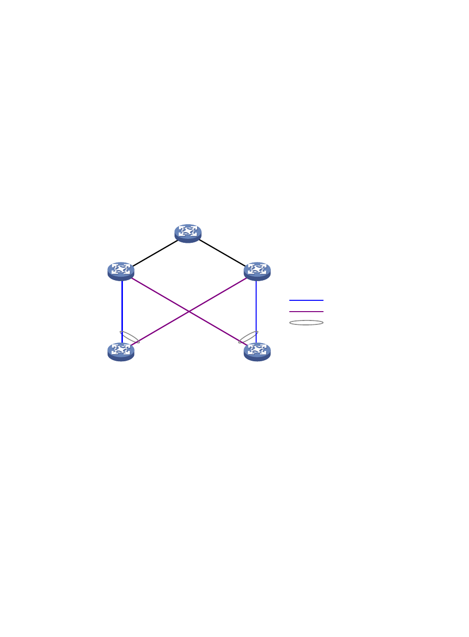
Network requirements
As shown in
:
•
Device C and Device D are smart link devices, and Device A, Device B, and Device E are
associated devices. Traffic of VLANs 1 through 30 on Device C and Device D are dually uplinked
to Device A.
•
Configure Smart Link on Device C and Device D for dual uplink backup.
Figure 26 Network diagram for single smart link group configuration
Device A
Device E
Device D
Device C
Device B
GE
1/0
/1
GE
1/0
/2
GE
1/0
/1
GE
1/0
/1
GE
1/0
/2
GE
1/0
/2
GE1/0/3
GE1/0/1
GE1/0/2
GE1/0/3
GE1/0/1
GE1/0/2
Master link
Slave link
Smart link group
Configuration procedure
1.
Configure Device C.
# Create VLANs 1 through 30, map these VLANs to MSTI 1, and activate the MST region configuration.
<DeviceC> system-view
[DeviceC] vlan 1 to 30
[DeviceC] stp region-configuration
[DeviceC-mst-region] instance 1 vlan 1 to 30
[DeviceC-mst-region] active region-configuration
[DeviceC-mst-region] quit
# Shut down GigabitEthernet 1/0/1 and GigabitEthernet 1/0/2, disable the spanning tree feature on
GigabitEthernet 1/0/1 and GigabitEthernet 1/0/2 separately, configure them as trunk ports, and
assign them to VLANs 1 through 30.
[DeviceC] interface gigabitethernet 1/0/1
[DeviceC-GigabitEthernet1/0/1] shutdown
[DeviceC-GigabitEthernet1/0/1] undo stp enable
[DeviceC-GigabitEthernet1/0/1] port link-type trunk
[DeviceC-GigabitEthernet1/0/1] port trunk permit vlan 1 to 30
[DeviceC-GigabitEthernet1/0/1] quit
- H3C S5800 Series Switches H3C S5820X Series Switches H3C WX3000E Series Wireless Switches H3C SecPath F1000-E H3C SecPath F5000-A5 Firewall H3C SecPath F1000-A-EI H3C SecPath F1000-E-SI H3C SecPath F1000-S-AI H3C SecPath F5000-S Firewall H3C SecPath F5000-C Firewall H3C SecPath F100-C-SI H3C SecPath F1000-C-SI H3C SecPath F100-A-SI H3C SecBlade FW Cards H3C SecBlade FW Enhanced Cards H3C SecPath U200-A U200-M U200-S H3C SecPath U200-CA U200-CM U200-CS