Dual homed rings configuration example, Networking requirements – H3C Technologies H3C S10500 Series Switches User Manual
Page 84
75
Dual homed rings configuration example
Networking requirements
As shown in
•
Device A through Device H form RRPP domain 1. Specify the primary control VLAN of RRPP domain
1 as VLAN 4092, and specify that RRPP domain 1 protects VLANs 1 through 30.
•
Device A through Device D form primary ring 1. Device A, Device B, and Device E form subring 2.
Device A, Device B, and Device F form subring 3. Device C, Device D, and Device G form subring
4. Device C, Device D, and Device H form subring 5.
•
Specify Device A as the master node of primary ring 1, GigabitEthernet 1/0/1 as the primary port
and GigabitEthernet 1/0/2 as the secondary port. Specify Device E as the master node of subring
2, GigabitEthernet 1/0/1 as the primary port and GigabitEthernet 1/0/2 as the secondary port.
Specify Device F as the master node of subring 3, GigabitEthernet 1/0/1 as the primary port and
GigabitEthernet 1/0/2 as the secondary port. Specify Device G as the master node of subring 4,
GigabitEthernet 1/0/1 as the primary port and GigabitEthernet 1/0/2 as the secondary port.
Specify Device H as the master node of subring 5, GigabitEthernet 1/0/1 as the primary port and
GigabitEthernet 1/0/2 as the secondary port.
•
Specify Device A as the edge node of the connected subrings, its GigabitEthernet 1/0/3 and
GigabitEthernet 1/0/4 as the edge ports. Specify Device D as the transit node of the primary ring
and edge node of the connected subrings, its GigabitEthernet 1/0/3 and GigabitEthernet 1/0/4
as the edge ports. Specify Device B and Device C as the transit node of the primary ring and
assistant-edge nodes of the connected subrings, their GigabitEthernet 1/0/3 and GigabitEthernet
1/0/4 as the edge ports.
NOTE:
Configure the primary and secondary ports on the master nodes properly to ensure that other protocols
still work normally when data VLANs are denied by the secondary ports.
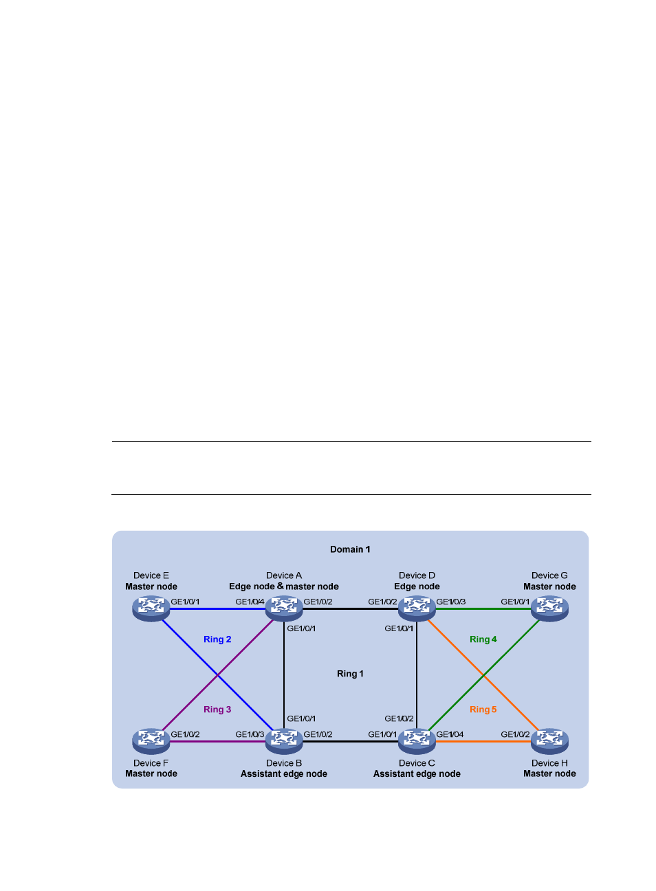
Figure 22 Network diagram for dual homed rings configuration
GE1/0/2
GE1/0/
1
GE1/
0/1
G
E1
/0/2
GE1/0/3
G
E1
/0/4
G
E1
/0/4
GE1/0/3
- H3C S5800 Series Switches H3C S5820X Series Switches H3C WX3000E Series Wireless Switches H3C SecPath F1000-E H3C SecPath F5000-A5 Firewall H3C SecPath F1000-A-EI H3C SecPath F1000-E-SI H3C SecPath F1000-S-AI H3C SecPath F5000-S Firewall H3C SecPath F5000-C Firewall H3C SecPath F100-C-SI H3C SecPath F1000-C-SI H3C SecPath F100-A-SI H3C SecBlade FW Cards H3C SecBlade FW Enhanced Cards H3C SecPath U200-A U200-M U200-S H3C SecPath U200-CA U200-CM U200-CS