Configuration procedure – H3C Technologies H3C S10500 Series Switches User Manual
Page 36
27
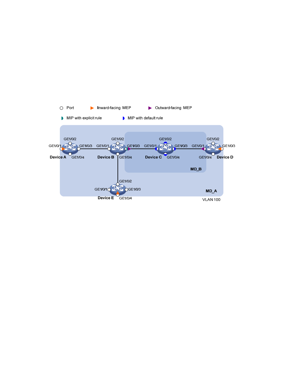
•
In MD_A, Device B is designed to have MIPs when its port is configured with low level MEPs. Port
GigabitEthernet 1/0/3 is configured with MEPs of MD_B, and the MIPs of MD_A can be
configured on this port. You should configure the MIP generation rule of MD_A as explicit.
•
The MIPs of MD_B are designed on Device C, and are configured on all ports. You should configure
the MIP generation rule as default.
•
Configure CC to monitor the connectivity among all the MEPs in MD_A and MD_B. Configure to
use LB to locate link faults.
•
After the status information of the entire network is obtained, use LT to identify path and locate
faults.
Figure 8 Network diagram for CFD configuration
Configuration procedure
1.
Configure a VLAN and assign ports to it.
, create VLAN 100, and assign ports GigabitEthernet 1/0/1 through
GigabitEthernet 1/0/4 to VLAN 100.
2.
Enable CFD.
# Enable CFD on Device A.
<DeviceA> system-view
[DeviceA] cfd enable
Enable CFD on Device B through Device E using the same method.
3.
Configure service instances.
# Create MD_A (level 5) on Device A, create MA_A, which serves VLAN 100, in MD_A, and create
service instance 1 for MD_A and MA_A.
[DeviceA] cfd md MD_A level 5
[DeviceA] cfd ma MA_A md MD_A vlan 100
[DeviceA] cfd service-instance 1 md MD_A ma MA_A
Configure Device E as you configure Device A.
- H3C S5800 Series Switches H3C S5820X Series Switches H3C WX3000E Series Wireless Switches H3C SecPath F1000-E H3C SecPath F5000-A5 Firewall H3C SecPath F1000-A-EI H3C SecPath F1000-E-SI H3C SecPath F1000-S-AI H3C SecPath F5000-S Firewall H3C SecPath F5000-C Firewall H3C SecPath F100-C-SI H3C SecPath F1000-C-SI H3C SecPath F100-A-SI H3C SecBlade FW Cards H3C SecBlade FW Enhanced Cards H3C SecPath U200-A U200-M U200-S H3C SecPath U200-CA U200-CM U200-CS