Vrrp interface tracking configuration example, Network requirements, Configuration procedure – H3C Technologies H3C S10500 Series Switches User Manual
Page 161
152
Admin Status : Up State : Master
Config Pri : 110 Running Pri : 110
Preempt Mode : Yes Delay Time : 5
Auth Type : None
Virtual IP : FE80::10
1::10
Virtual MAC : 0000-5e00-0201
Master IP : FE80::1
The output shows that after Switch A resumes normal operation, it becomes the master, and packets sent
from host A to host B are forwarded by Switch A.
VRRP interface tracking configuration example
Network requirements
•
Switch A and Switch B belong to VRRP group 1 with the virtual IP addresses of 1::10/64 and
FE80::10.
•
Host A wants to access Host B on the Internet, and learns 1::10/64 as its default gateway through
RA messages sent by the switches.
•
When Switch A operates normally, packets sent from Host A to Host B are forwarded by Switch A.
If VLAN-interface 3 through which Switch A connects to the Internet is not available, packets sent
from Host A to Host B are forwarded by Switch B.
•
To prevent attacks to the VRRP group from illegal users by using spoofed packets, configure the
authentication mode as plain text to authenticate the VRRP packets in VRRP group 1, and specify the
authentication key as hello.
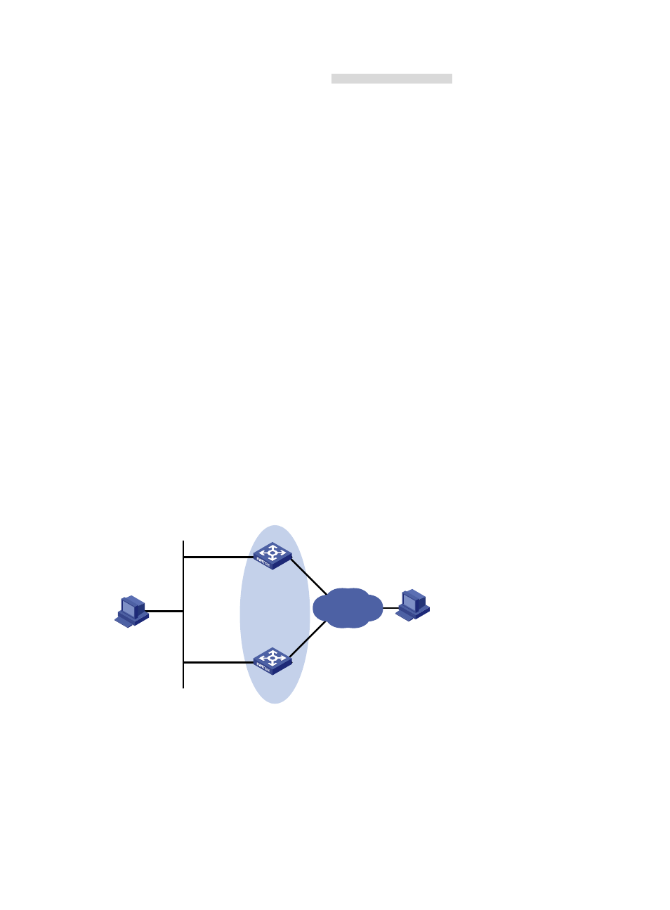
Figure 41 Network diagram for VRRP interface tracking
Host A
Switch A
Switch B
Virtual IPv6 address:
FE80::10
1::10/64
Vlan-int2
FE80::1
1::1/64
Vlan-int2
FE80::2
1::2/64
Host B
Gateway:
1::10/64
Vlan-int3
Internet
Configuration procedure
1.
Configure Switch A
# Configure VLAN 2.
<SwitchA> system-view
[SwitchA] ipv6
[SwitchA] vlan 2
- H3C S5800 Series Switches H3C S5820X Series Switches H3C WX3000E Series Wireless Switches H3C SecPath F1000-E H3C SecPath F5000-A5 Firewall H3C SecPath F1000-A-EI H3C SecPath F1000-E-SI H3C SecPath F1000-S-AI H3C SecPath F5000-S Firewall H3C SecPath F5000-C Firewall H3C SecPath F100-C-SI H3C SecPath F1000-C-SI H3C SecPath F100-A-SI H3C SecBlade FW Cards H3C SecBlade FW Enhanced Cards H3C SecPath U200-A U200-M U200-S H3C SecPath U200-CA U200-CM U200-CS