Configuration procedure – H3C Technologies H3C S10500 Series Switches User Manual
Page 184
175
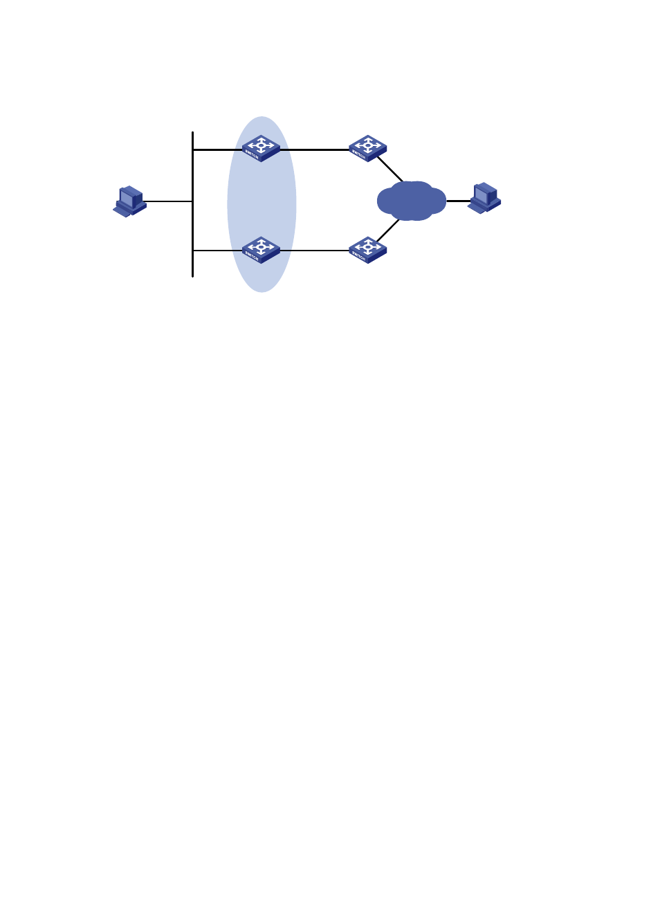
Figure 47 Network diagram for VRRP-track-NQA collaboration configuration
Host A
Switch A
Switch B
Virtual IP address:
10.1.1.10/24
Vlan-int2
10.1.1.1/24
Vlan-int2
10.1.1.2/24
Host B
10.1.1.3/24
20.1.1.1/24
Internet
Vlan-int3
10.1.2.1/24
Vlan-int3
10.1.3.1/24
Vlan-int3
10.1.3.2/24
Vlan-int3
10.1.2.2/24
Switch C
Switch D
Configuration procedure
1.
Create VLANs, and assign corresponding ports to the VLANs. Configure the IP address of each
. (Details not shown)
2.
Configure an NQA test group on Switch A.
<SwitchA> system-view
# Create an NQA test group with the administrator name admin and the operation tag test.
[SwitchA] nqa entry admin test
# Configure the test type as ICMP-echo.
[SwitchA-nqa-admin-test] type icmp-echo
# Configure the destination address as 10.1.2.2.
[SwitchA-nqa-admin-test-icmp-echo] destination ip 10.1.2.2
# Set the test frequency to 100 ms.
[SwitchA-nqa-admin-test-icmp-echo] frequency 100
# Configure reaction entry 1, specifying that five consecutive probe failures trigger the track module.
[SwitchA-nqa-admin-test-icmp-echo] reaction 1 checked-element probe-fail threshold-type
consecutive 5 action-type trigger-only
[SwitchA-nqa-admin-test-icmp-echo] quit
# Start the NQA test.
[SwitchA] nqa schedule admin test start-time now lifetime forever
3.
Configure a track entry on Switch A.
# Configure track entry 1, and associate it with reaction entry 1 of the NQA test group (with the
administrator admin, and the operation tag test).
[SwitchA] track 1 nqa entry admin test reaction 1
4.
Configure VRRP on Switch A.
# Create VRRP group 1, and configure the virtual IP address 10.1.1.10 for the group.
[SwitchA] interface vlan-interface 2
[SwitchA-Vlan-interface2] vrrp vrid 1 virtual-ip 10.1.1.10
# Set the priority of Switch A in VRRP group 1 to 110.
- H3C S5800 Series Switches H3C S5820X Series Switches H3C WX3000E Series Wireless Switches H3C SecPath F1000-E H3C SecPath F5000-A5 Firewall H3C SecPath F1000-A-EI H3C SecPath F1000-E-SI H3C SecPath F1000-S-AI H3C SecPath F5000-S Firewall H3C SecPath F5000-C Firewall H3C SecPath F100-C-SI H3C SecPath F1000-C-SI H3C SecPath F100-A-SI H3C SecBlade FW Cards H3C SecBlade FW Enhanced Cards H3C SecPath U200-A U200-M U200-S H3C SecPath U200-CA U200-CM U200-CS