Rear panel, S5800-56c-pwr panel views, Front panel – H3C Technologies H3C S5800 Series Switches User Manual
Page 19
9
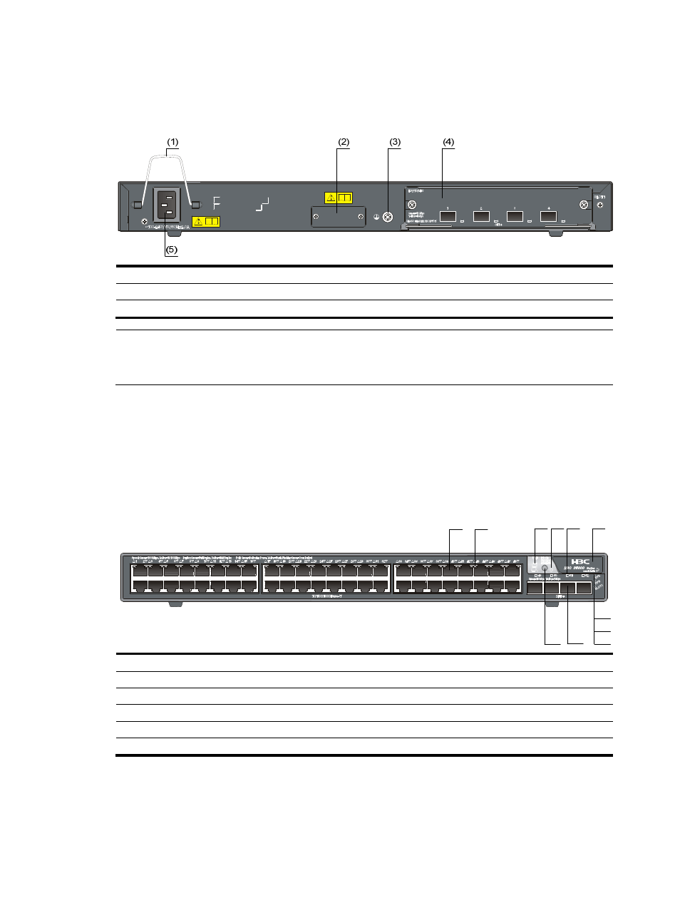
Rear panel
Figure 6 S5800-56C rear panel
(1) Bail latch
(2) RPS DC-input power receptacle
(3) Grounding screw
(4) Expansion interface card slot
(5) AC-input power receptacle
NOTE:
The S5800-56C switch comes with the expansion interface card slot covered by a filler panel. In this
figure, an LSW1SP4P0 interface card is installed in the slot.
S5800-56C-PWR panel views
Front panel
Figure 7 S5800-56C-PWR front panel
(1) 10/100/1000Base-T auto-sensing Ethernet port
(2) 10/100/1000Base-T Ethernet port LED
(3) Seven-segment LED
(4) Port mode LED
(5) SFP+ port LED
(6) Logo plate (A console port and a USB port are under this logo plate)
(7) System status LED (SYS)
(8) RPS status LED (RPS)
(9) Interface card status LED (SLOT1)
(10) SFP+ port
(11) Port LED mode switching button
To use the console port and USB port, open the logo plate, as shown in
.
(1)
(2)
(3) (4) (5)
(6)
(7)
(8)
(9)
(11) (10)