Connecting the psr150-a/psr150-a1, Figure 61 – H3C Technologies H3C S5800 Series Switches User Manual
Page 69
59
2.
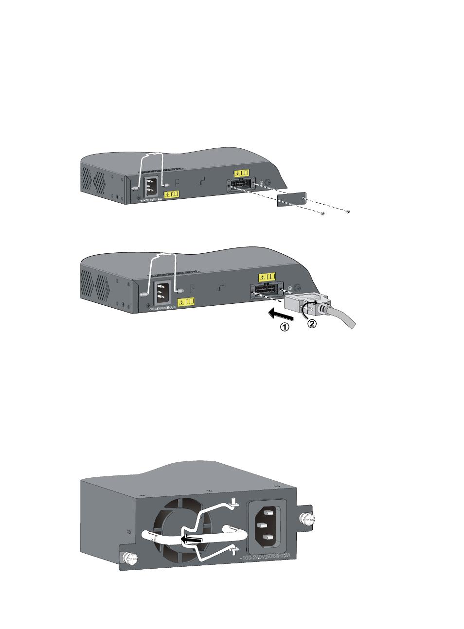
Unpack the RPS power cord, identify the plug for connecting to the switch, correctly orient the plug
with the RPS DC-input receptacle on the switch chassis, and insert the plug into the receptacle (see
callout 1 in
). The power receptacle is foolproof. If you cannot insert the plug into the
receptacle, re-orient the plug rather than use excessive force to push it in.
3.
Tighten the screws on the plug with a flat-blade screwdriver to secure the plug in the power
receptacle (see callout 2 in
4.
Connect the other end of the power cord to the RPS.
Figure 61 Connect the S5800-56C/S5800-32C switch to a 12 VDC output RPS (I)
Figure 62 Connect the S5800-56C/S5800-32C switch to a 12 VDC output RPS (II)
Connecting the PSR150-A/PSR150-A1
1.
Pull the bail latch leftwards (see
).
2.
Connect one end of the AC power cord supplied with the power module to the power receptacle
on the power module (see callout 1 in
).
3.
Pull the bail latch rightwards to secure the plug to the power receptacle (see callout 2 in
).
4.
Connect the other end of the power cord to an AC power outlet.
Figure 63 Connect an AC power cord to the PSR150-A/PSR150-A1 (I)