Airflow design for the sr8808 – H3C Technologies H3C SR8800 User Manual
Page 25
15
Airflow design for the SR8802 and SR8805 and SR8812
The chassis and power modules of the SR8802, SR8805, and SR8812 routers use separate air aisles.
The airflow for the power module section at the bottom is from front to rear, and the airflow for the chassis
is from left to right, as shown in
Figure 15 SR8805 airflow
(1) Chassis air intake
(2) Chassis air outlet
(3) Power module air intake
(4) Power module air outlet
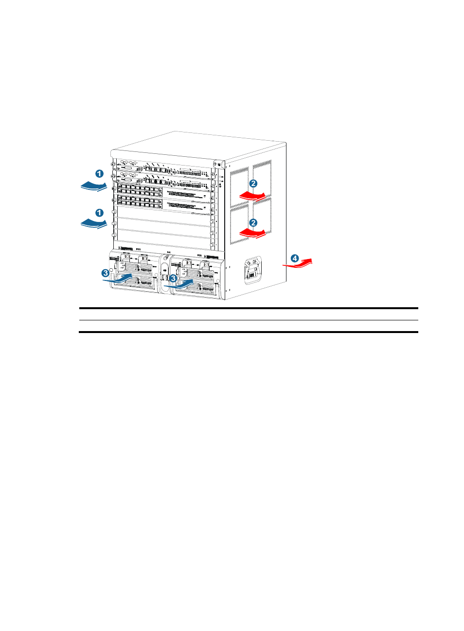
Airflow design for the SR8808
The chassis and power modules of the SR8808 router use separate aisles. For the power module section
at the bottom, air flows from front to rear, and for the chassis, air flows in through the air intake vents at
the lower rear and front of the chassis, and exhausts out the side air outlets and rear air outlets at the top
of the chassis, as shown in
.