HEIDENHAIN CNC Pilot 4290 Pilot User Manual
Page 16
16
Undercut contour G25-Geo
G25 generates the following undercut contours in paraxial contour
corners. The meaning of the parameters depends on the type of
undercut.
If you program G25
■
after the reference element, the undercut is turned at the end of the
reference element.
■
before the reference element, the undercut is turned at the
beginning of the reference element.
Calling the contour macro (example):
N..G1 Z..
/Linear element as reference
N..G25 H..I..K.. .. /Undercut contour
N..G1 X..
/Next surface element
Parameters
Continued
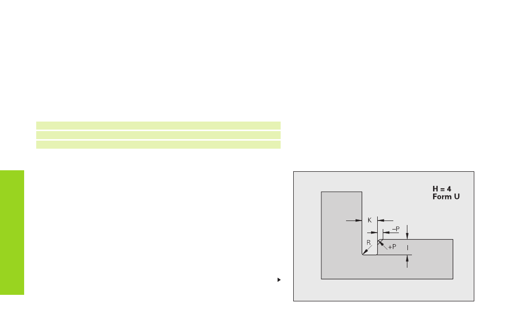
Undercut form U (H=4)
Undercut form U (H=4)
Parameters
I:
Depth of undercut (radius)
K:
Width of undercut
R:
Inside radius (in both corners of recess) – default: 0
P:
Outside radius/chamfer – default: 0
■
P>0: radius of the rounding
■
P<0: width of the chamfer
F
o
rm
elements
fo
r cont
our descr
iption
H:
Type of undercut – default: 0
■
H=4: undercut form U
■
H=0, 5: undercut form DIN 509 E
■
H=6: undercut form DIN 509 F
■
H=7: thread undercut DIN 76
■
H=8: undercut form H
■
H=9: undercut form K