HEIDENHAIN CNC Pilot 4290 Pilot User Manual
Page 67
67
Contour-parallel roughing G830
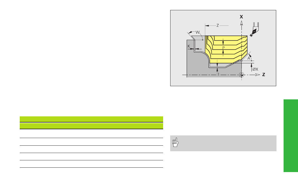
G830 machines (roughs) the contour area defined by ”NS, NE” parallel
to the contour.
Parameters
NS, NE: Starting block number, end block number (from the contour
description)
P:
Maximum approach - Maximum infeed distance
I, K:
Allowances (I diameter value) – default: 0
X/Z:
Cutting limit (X diameter value)
A, W: Approach angle, departure angle (reference: Z axis)
■
Approach angle – default: 0°/180° (parallel to Z axis)
■
Departure angle – default: 90°/270° (perpendicular to Z axis)
Q:
Type of retraction after machining – default: 0
■
Q=0: return to starting point (first X and then Z direction)
■
Q=1: position in front of finished contour
■
Q=2: move to clearance height and stop
V:
Machining chamfers/roundings at start/end of contour – default:
0; chamfer/rounding is machined:
■
V=0: at beginning and end
Cont
our
-det
er
mined
tu
rning cy
cles
D
G22
G23
G23
G25
G25
G25
=
H0
H1
H4
H5/6
H7..9
0
•
•
•
•
•
•
1
•
•
•
–
–
–
2
•
•
–
•
•
•
3
•
•
–
–
–
–
4
•
•
–
–
•
–
„•“: Skipping elements
■
V=1: at beginning
■
V=2: at end
■
V=3: no machining at start or end
■
V=4: only single chamfers/roundings are
machined – not the base element
(requirement: the contour consists of a
contour element)
D:
Omit element (influences the machining of
undercuts, free rotations: see table) – default: 0
• Cutter radius compensation: is carried out
• Offsets (G57/G58): are effective