Connection diagram, 5 installation procedure – Yaskawa 1000 Series Drive Option - CC-Link Technical Manual User Manual
Page 12
5 Installation Procedure
12
YASKAWA ELECTRIC SIEP C730600 44A YASKAWA AC Drive-Option Card CC-Link Technical Manual
◆
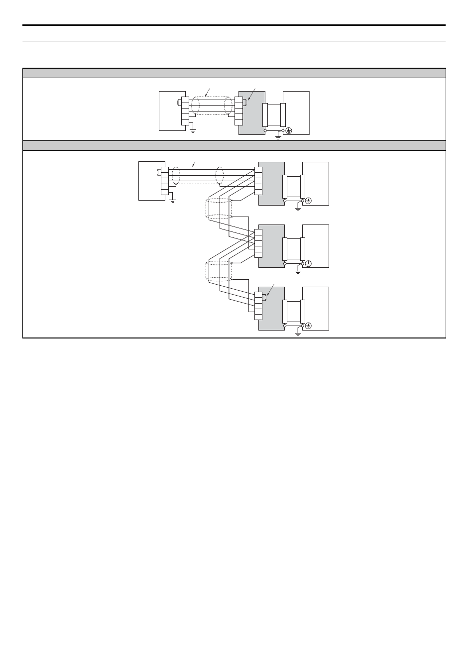
Connection Diagram
Table 4 Connection Diagram
Using a single drive
<1> The user must set up the drive for terminal resistor. For instructions, see
Terminal Resistor Connection on page 15
<2> Make sure that the FG terminal on the master drive is grounded properly.
<3> The FE terminal on the CC-Link Option is supplied with a ground cable that should be connected to the ground terminal on the drive.
Using multiple drives
CC-Link
Option
DA
DB
DG
SLD
SLD
DA
DB
DG
SLD
FG
Master
device
CC-Link cable
DRIVE
Terminal resistor
<1>
FE
<2>
<3>
CC-Link
Option
DA
DB
DG
SLD
SLD
CC-Link
Option
DA
DB
DG
SLD
SLD
DA
DB
DG
SLD
FG
CC-Link
Option
DA
DB
DG
SLD
SLD
Master
device
DRIVE
DRIVE
DRIVE
CC-Link cable
Terminal resistor
<1>
FE
FE
FE
<2>
<3>
<3>
<3>