Prior to installing the option card, Installing the cc-link option – Yaskawa 1000 Series Drive Option - CC-Link Technical Manual User Manual
Page 13
5 Installation Procedure
YASKAWA ELECTRIC
SIEP C730600 44A YASKAWA AC Drive-Option Card CC-Link Technical Manual
13
◆
Prior to Installing the Option Card
Prior to installing the DeviceNet Option, wire the drive and make necessary connections to the drive terminals. Refer to the Quick Start Guide for
the drive the CC-Link Option is connected to for information on wiring and connecting the drive. Verify that the drive runs normally without the
option installed.
◆
Installing the CC-Link Option
This CC-Link Option can be inserted into the either only CN5-A connectors located on the drive’s control board.
See the drive manual for directions on removing the front cover.
1.
Shut off power to the drive, wait the appropriate amount of time for voltage to dissipate, then remove the operator and front cover.
2.
Insert the CN5 connector on the CC-Link Option into the matching CN5 connector on the drive, then fasten it into place using one of the
screws included with the CC-Link Option.
Connect one of the lead lines using one of the screws to the ground terminal.
Three separate lead lines have been included with the CC-Link Option to connect to three separate ports. Use the lead line with the length
appropriate for the distance of the port.
Note: There are only two screw holes on the drive for ground terminals. If three option cards are connected, two of the lead lines will need to share the same ground terminal.
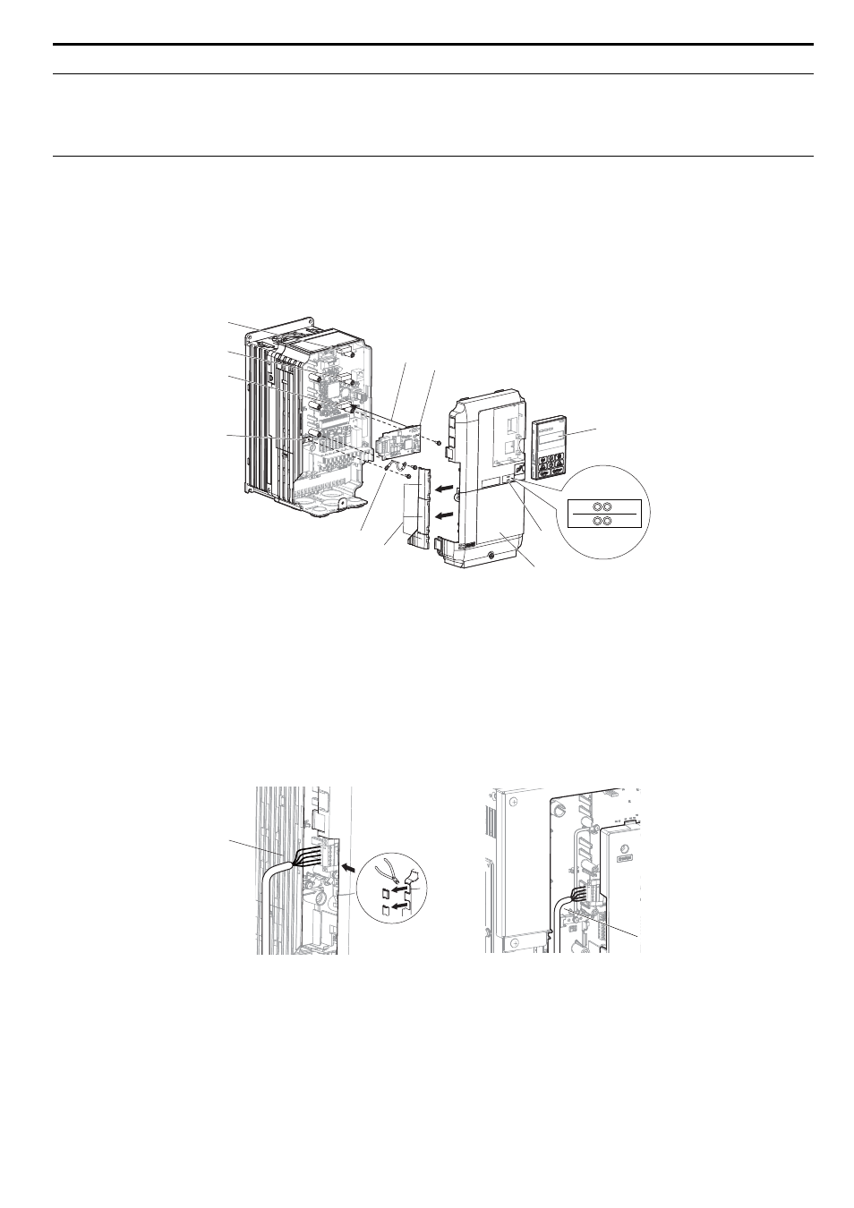
Figure 4
Figure 4 Installing the Option
3.
Wire the CC-Link Option to the terminal block on the CC-Link Option.
For wiring instructions, see
.
For exposed cables in drives 2A004 to 0069, 4A0002 to 0044, use a pair of wire cutters to create an opening on the left side of the front
cover that allows wiring to pass through. Sharp edges along the opening that was created should be smoothed down with a file or sand
paper so prevent any damage to the wires.
Drives 2A0081 to 0021, 4A0058 to 0165 have enough space to keep all wiring inside the unit.
Figure 5
Figure 5 Wiring space
4.
Place the front cover back onto the drive as it was before.
Note: 1. Take care when wiring the CC-Link Option so that the front cover easily fits back onto the drive.
2. Install Cable Cover option to maintain the drive Enclosure Type.
A – Connector CN5-C
G – Lead line
B – Connector CN5-B
H – Use wire cutters to create an
opening for cable lines
C – Connector CN5-A
I – Operator
D – Drive grounding terminal (FE)
J – LED label
E – Insert connector CN5 here
K – Front cover
F – CC-Link Option
A – Cable through hole
(2A0004 to 0069, 4A0002 to 0044)
B – Space for wiring
(2A0081 to 0021, 4A0058 to 0165)
REV
DRV
LERR
FOUT
G
A
E
F
I
J
B
C
D
H
K
B
A