Drive, I.3 electrical installation safety – Yaskawa AC Drive Z1000 HVAC User Manual
Page 15
+
-
+
+
-
+
-
SN
AM
FM
V
I
<1>
M
U/T
1
V/T
2
W/T
U
V
W
3
Ground
Cooling fan
M
+
-
+
+
-
+
-
S
1
S
2
S
3
S
4
S
5
S
6
S
7
FE
A
1
A
2
0
V
AC
R
R
S
S-
IG
Drive
2
k
FM
AM
0
V
FM
AM
AC
FE
<9>
<9>
<7>
<7>
<8>
<6>
<3>
<2>
+
V
MA
M
1
M
2
MB
MC
CN5
Forward Run / Stop
Reverse Run / Stop
External fault
Fault reset
Multi-speed step 1
Multi-speed step 2
Jog speed
Multi-function
digtial inputs
(default setting)
Option card
connector
Shield ground terminal
Multi-function
analog inputs
Power supply +10.5 Vdc, max. 20 mA
Analog Input 1
(Frequency Reference Bias)
0 to +10 Vdc (20 k
W)
4 to 20 mA / 0 to 20 mA (250 )
Analog Input 2
(Frequency Reference Bias)
0 to +10 Vdc (20 k
W)
4 to 20 mA / 0 to 20 mA (250 )
+
P
Externalpower supply,
24 Vdc, max. 150 mA
Termination resistor
(120 , 1/2 W)
DIP
Switch S2
Fault relay output
250 Vac, max. 2 A
30 Vdc, max 2 A
(min. 5 Vdc, 10 mA)
Multi-function relay output (During Run)
250 Vac, max. 2 A
30 Vdc, max 2 A
(min. 5 Vdc, 10 mA)
Multi-function analog output 1
(Output frequency)
0 to +10 Vdc (2 mA)
4 to 20 mA
Multi-function analog output 2
(Output current)
0 to +10 Vdc (2 mA)
4 to 20 mA
Main Circuit
Control Circuit
shielded line
twisted-pair shielded line
main circuit terminal
control circuit terminal
r1
s1
t1
FU
FV
FW
R/L
1
S/L
2
T/L
+M
-M
3
Three-phase
power supply
200 V/400 V
50/60 Hz
Wiring sequence should shut off
power to the drive when a fault
output is triggered.
<10>
M
3
M
4
Multi-function relay output (Zero Speed)
250 Vac, max. 2 A
30 Vdc, max 2 A
(min. 5 Vdc, 10 mA)
M
5
M
6
Multi-function relay output (Speed Agree 1)
250 Vac, max. 2 A
30 Vdc, max 2 A
(min. 5 Vdc, 10 mA)
A2
A1
V
I
Jumper S1
A1/A2 Volt./Curr.
Selection
R
S
T
Main
Switch
Fuse
12-Pulse/18-Pulse
Rectification
Jumper S5
AM/FM Volt./Curr.
Selection
SC
<4>
+
24 V
Sink / Source mode
selection wire link
(default: Sink)
SP
<5>
ON
SW1
OFF
ON
SW2
OFF
APOGEE FLN Comm.
RS-422/RS-485
48 kbps
BACnet Comm.
RS-485
max. 76.8 kbps
MEMOBUS/Modbus
comm. RS-422/RS-485
max. 115.2 kbps
Metasys N2 Comm.
RS-422/RS-485
96 kbps
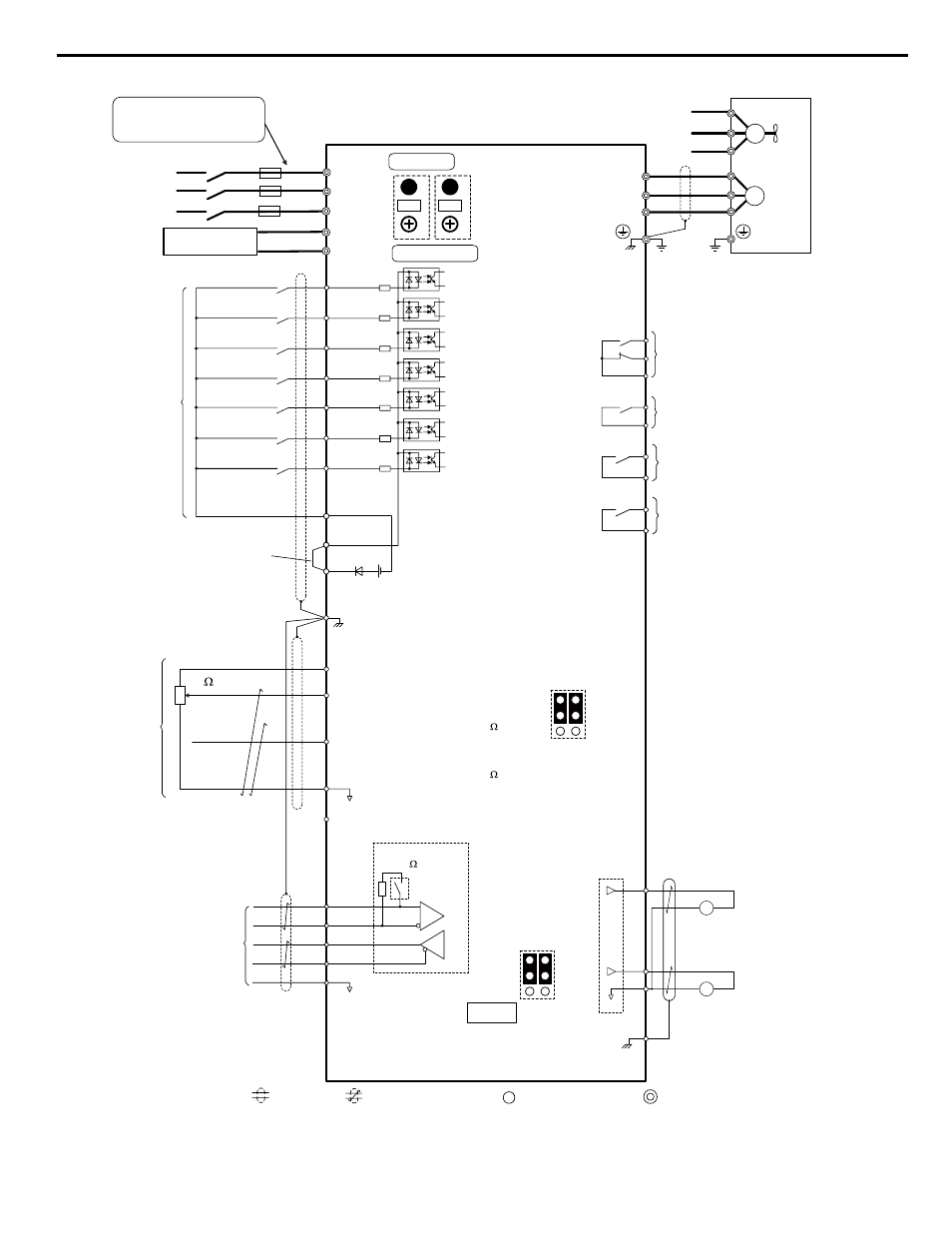
Figure i.3 Drive Standard Connection Diagram (example: 2A0011)
<1> Self-cooling motors do not require the same wiring necessary for motors with cooling fans.
i.3 Electrical Installation Safety
YASKAWA ELECTRIC TOEP YAIZ1U 01A YASKAWA AC Drive – Z1000 Safety Precautions
15