Control circuit terminal block functions, Terminal configuration, Control circuit input terminals – Yaskawa AC Drive Z1000 HVAC User Manual
Page 28
u
Control Circuit Terminal Block Functions
Drive parameters determine which functions apply to the multi-function digital inputs (S1 to S7), multi-function digital outputs
(M1 to M6), multi-function analog inputs (A1 and A2), and multi-function analog monitor output (FM, AM). The default
setting is listed next to each terminal in
WARNING! Sudden Movement Hazard. Always check the operation and wiring of control circuits after being wired. Operating a drive with
untested control circuits could result in death or serious injury.
WARNING! Sudden Movement Hazard. Confirm the drive I/O signals and external sequence before starting test run. Setting parameter
A1-06 may change the I/O terminal function automatically from the default setting. Failure to comply may result in death or serious injury.
u
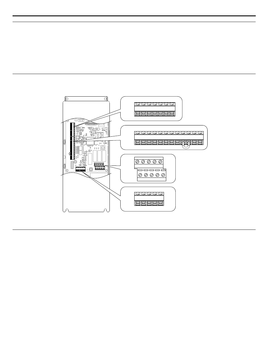
Terminal Configuration
The control circuit terminals are arranged as shown in
TB3
TB1
TB2
TB4
+V AC A1 A2 FM AM AC
S1 S2 S3 S4 S5 S6 S7 SN SC SP +P FE
IG R+ R- S+ S-
M3 M4 M5 M6
MA MBMC M1 M2
Figure i.14 Control Circuit Terminal Arrangement
u
Control Circuit Input Terminals
lists the input terminals on the drive. Text in parenthesis indicates the default setting for each multi-function input.
i.3 Electrical Installation Safety
28
YASKAWA ELECTRIC TOEP YAIZ1U 01A YASKAWA AC Drive – Z1000 Safety Precautions