Main circuit wiring, Main circuit terminal functions, Pulse/18-pulse rectification – Yaskawa AC Drive Z1000 HVAC User Manual
Page 17: Notice
u
Main Circuit Wiring
WARNING! Electrical Shock Hazard. Do not connect the AC power line to the drive output terminals U/T1, V/T2, and W/T3 . Failure to
comply could result in death or serious injury by fire as a result of drive damage from line voltage application to output terminals.
NOTICE
Refer to the Z1000 User Manual TOEPC71061645 on the CD-ROM packaged with the product for complete product
instructions necessary for proper installation, set-up, troubleshooting and maintenance. CD part number TOECC71061615.
NOTICE: Route motor leads U/T1, V/T2, and W/T3 separate from all other leads to reduce possible interference related issues. Failure to
comply may result in abnormal operation of drive and nearby equipment.
NOTICE: Do not use the negative DC bus terminal “–” as a ground terminal. This terminal is at high DC voltage potential. Improper wiring
connections could damage the drive.
NOTICE: Do not solder the ends of wire connections to the drive. Soldered wiring connections can loosen over time. Improper wiring practices
could result in drive malfunction due to loose terminal connections.
NOTICE: Do not switch the drive input to start or stop the motor. Frequently switching the drive on and off shortens the life of the DC bus
charge circuit and the DC bus capacitors, and can cause premature drive failures. For the full performance life, refrain from switching the
drive on and off more than once every 30 minutes.
NOTICE: When connecting the motor to the drive output terminals U/T1, V/T2, and W/T3, the phase order for the drive and motor should
match. Failure to comply with proper wiring practices may cause the motor to run in reverse if the phase order is backward.
NOTICE: Do not connect phase-advancing capacitors or LC/RC noise filters to the output circuits. Failure to comply could result in damage
to the drive, phase-advancing capacitors, LC/RC noise filters or ground fault circuit interrupters.
Note:
Wire gauge recommendations based on drive continuous current ratings (ND) using 75 °C 600 Vac vinyl-sheathed wire assuming ambient
temperature within 40 °C and wiring distance less than 100 m.
Note:
The mark indicates the terminals for protective ground connection as defined in IEC/EN 60417-5019.
Grounding impedance:
200 V: 100 Ω or less
400 V: 10 Ω or less
u
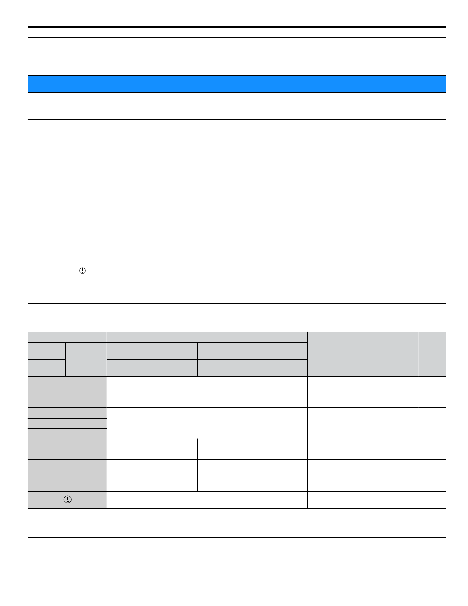
Main Circuit Terminal Functions
Table i.3 Main Circuit Terminal Functions
Terminal
Type
Function
Page
200 V
Class
Drive
Model
2A0011 to 2A0273
2A0343 and 2A0396
400 V
Class
4A0005 to 4A0302
4A0361 to 4A0590
R/L1
Main circuit power supply input
Connects line power to the drive
S/L2
T/L3
U/T1
Drive output
Connects to the motor
V/T2
W/T3
+1
–
DC power supply input (+1 and –) or
12/18 pulse rectification
For connecting peripheral devices
–
–
+3
<1>
–
–
–
–
+M
12/18 pulse rectification
<2>
–
Input for 12/18 pulse rectification
–
-M
For 200 V class: 100 Ω or less
For 400 V class: 10 Ω or less
Grounding terminal
<1> Not used.
<2> Not available for common DC bus systems.
u
12-Pulse/18-Pulse Rectification
Operation with 12-pulse/18-pulse rectification requires the user to separately prepare a 3-winding/4-winding transformer for
the power supply. Contact Yaskawa or your nearest sales representative for the transformer specifications.
i.3 Electrical Installation Safety
YASKAWA ELECTRIC TOEP YAIZ1U 01A YASKAWA AC Drive – Z1000 Safety Precautions
17