4 profibus-dp option components, Profibus-dp option, Figure 2 – Yaskawa PG-X2G5 User Manual
Page 12: 4profibus-dp option components
12
YASKAWA ELECTRIC TOBP C730600 23C 1000-Series Option SI-P3/V, SI-P3/T Installation Manual
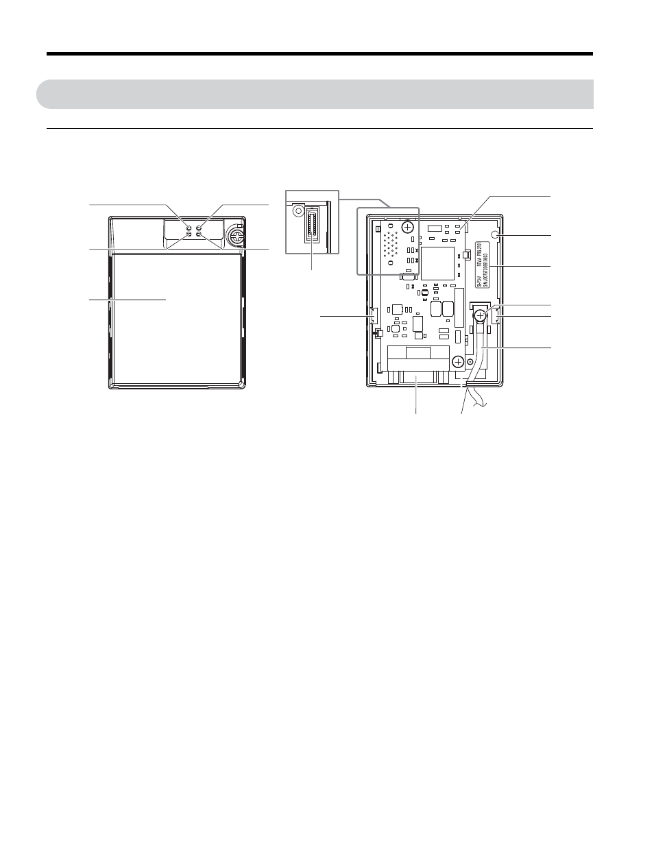
4 PROFIBUS-DP Option Components
4
PROFIBUS-DP Option Components
◆
PROFIBUS-DP Option
Figure 2
Figure 2 Option Unit
Note: For details on the LEDs,
Refer to PROFIBUS-DP Option LED Display on page 15
.
A – LED (Comm: green)
<1> Cables are not connected to the PROFIBUS-DP Option and are packaged separately in the box.
H – Nameplate
B – LED (BF: red)
I – Function Earth cable connection
(FE)
C – Option cover
J – Mounting clip
D – LED (ERR: red)
K – Cable
E – LED (RUN: green)
L – Through-hole for cable
F – PROFIBUS-DP PCB
M – Communication cable connector
(9-pin D-SUB)
G – Attachment screw hole for
option cover
N – Option board connector
N
J
G
F
J
I
K
L
PROFIBUS-DP with cover removed
Underside
M
SI-P3
FE
A
E
D
B
C
PROFIBUS-DP with cover attached
H
RUN
ERR
COMM
BF