7 profibus-dp option data and i/o maps – Yaskawa PG-X2G5 User Manual
Page 29
7 PROFIBUS-DP Option Data and I/O Maps
YASKAWA ELECTRIC TOBP C730600 23C 1000-Series Option SI-P3/V, SI-P3/T Installation Manual
29
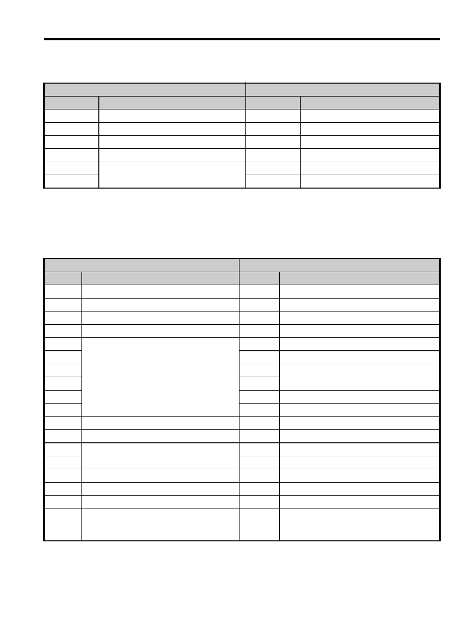
Table 9 Basic Data Register Map Detail
Table 10 Extended Data 1 Register Map
Output (Master Device to Drive)
Input (Drive to Master Device)
Byte
<1> Unit depends on the setting of o1-03 (Digital Operator Display Scaling). When the drive is operating in the V/f
Control mode, the drive's output frequency becomes the input data.
<2> Data is displayed in units of either 0.01 A for drives 7.5 kW and smaller, or in units of 0.1 A for drives 11 kW and
larger. This is the same regardless of whether the drive is set for Normal Duty or Heavy Duty operation.
Description
Byte
Description
0
Operation Command (High Byte)
0
Drive Status (High Byte)
1
Operation Command (Low Byte)
1
Drive Status (Low Byte)
2
Frequency Reference (High Byte)
2
Motor Speed (High Byte)
3
Frequency Reference (Low Byte)
3
Motor Speed (Low Byte)
4
Reserved
4
Output Current (High Byte)
5
5
Output Current (Low Byte)
Output (Master Device to Drive)
Input (Drive to Master Device)
Byte
Description
Byte
Description
0
Operation Command (High Byte)
0
Drive Status (High Byte)
1
Operation Command (Low Byte)
1
Drive Status (Low Byte)
2
Frequency Reference (High Byte)
2
Motor Speed (High Byte)
3
Frequency Reference (Low Byte)
3
Motor Speed (Low Byte)
4
Reserved
4
Torque Reference Monitor (High Byte)
5
5
Torque Reference Monitor (Low Byte)
6
6
Reserved
7
7
8
8
Frequency Reference (High Byte)
9
9
Frequency Reference (Low Byte)
10
Analog Output Channel 1 (High Byte)
10
Output Frequency (High Byte)
11
Analog Output Channel 1 (Low Byte)
11
Output Frequency (Low Byte)
12
Reserved
12
Output Current (High Byte)
13
13
Output Current (Low Byte)
14
Digital Output (High Byte)
14
Analog Input Channel 1 (High Byte)
15
Digital Output (Low Byte)
15
Analog Input Channel 1 (Low Byte)
16
MEMOBUS/Modbus Function Code
16
MEMOBUS/Modbus Function Code
17
MEMOBUS/Modbus Starting Register
Address
(High Byte)
17
MEMOBUS/Modbus Starting Register
Address
(High Byte)