Connection diagram, 5 installation procedure – Yaskawa PG-X2G5 User Manual
Page 19
5 Installation Procedure
YASKAWA ELECTRIC TOBP C730600 23C 1000-Series Option SI-P3/V, SI-P3/T Installation Manual
19
◆
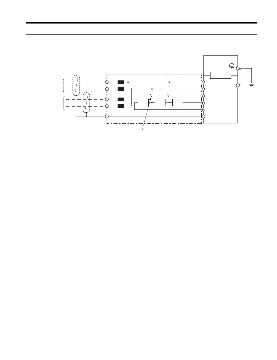
Connection Diagram
Figure 5
Figure 5 Connection Diagram
■
PROFIBUS-DP Termination
Because the PROFIBUS-DP Option does not have a termination resistor, a termination
resistance must be set using a switch on the 9 pin D-sub connector. Make sure that only the
D-sub connector for the last or end drive in the network has a terminating resistor. If any
other drive on the network has a terminating resistor, communication problems may occur.
Most 9 pin D-sub connectors have a function for disconnecting the output side of the cable.
Use only the input side cable entry when connecting both ends of the network. If the
connector is reversed, then communication will not be possible between devices. Most
connectors have arrows indicating the input and output sides.
Terminating resistors are shown in
can only be used. for baud rates below 1.5
Mbps. 1.5 Mbps and higher baud rates require termination with resistors as shown in
<1> The FE terminal on the PROFIBUS-DP Option is fitted with a ground cable that should be connected to the
ground terminal on the drive.
Drive
9-pin D-SUB Connector
For the last node on the bus,
turn on the termination resistor switch.
PROFIBUS-DP
Option
RTS
DGND
VP
A-line
B-line
390W 220W
390W
1B
1A
3
8
4
6
5
2B
2A
CN5
FE
<1>
PROFIBUS Cable
PROFIBUS Cable Connector
(Red)
(Green)
(Red)
(Green)
(Shell)
To PROFIBUS-DP
Master
To the next slave
(Shell)