iSys iTerra Lite Color Inkjet Printer User Manual
Page 32
32
screwdriver. Install the replacement screws and tighten firmly. Properly installed screws will
protrude from printer approximately ¼ “ from the printer front plate. Refer to figures ‘Install19 &
Install20’ for clarity.
d) Hang the tray portion of the output tray over the new screws installed in step a.
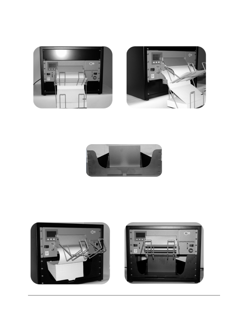
Figure # Install 21
Figure # Install 22
Properly installed input and output media are in the ‘Install21 and Install22’ figures. When the
paper is properly fed into the printer (first sheet being a non I-mark sheet), output collection will be
uniform and stacked as expected. The output tray will stack or fold up to 500 API sheets
maximum.
INSTALLATION OF OPTIONAL RACK INPUT BOTTOM TRAY (FOR RACK INSTALL ONLY)
Figure # Install 23
Rack Input Bottom Tray – (Rack Mount only) iSys Part# KIT-PPR-ITL1000
Installation of the rack input bottom tray is best performed by a technician with experience. The
rack input bottom tray ships with no additional rack hardware. Mounting of the rack input bottom
tray is intended to be placed in a rack immediately below the iTerra Lite printer. Failure to mount
as described may result in improper media feed to the printer. Figures ‘Install24 and Install25’
show the installed rack input bottom tray accompanied with the optional output media tray).
Figure # Install 24
Figure # Install 25