Mp e – Magnum Energy Magnum Panel (MP Series) User Manual
Page 32
© 2011 Magnum Energy, Inc.
Page 25
3.0 Installation
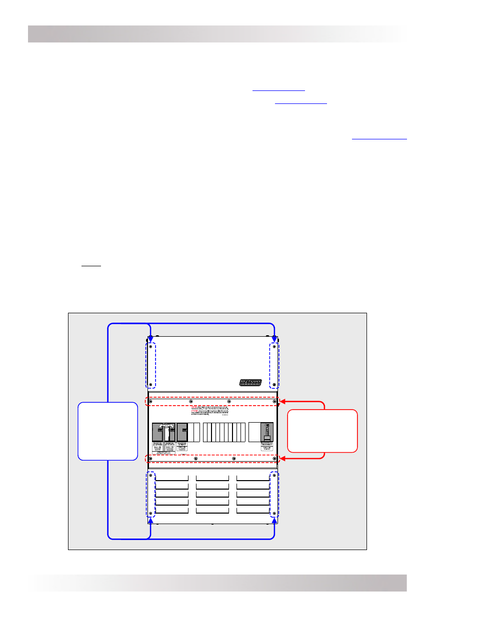
Remove the
upper four and
lower four Pan
head screws
(eight total)
to remove the
front cover.
DO NOT remove
these eight Truss
head screws to
remove the front
cover.
3.3 Preparing the MP Enclosure and Inverter
Prior to mounting any component, the installation will be easier if you prepare the MP enclosure
and the Magnum inverter by performing the following:
• Remove the MP enclosure front cover as described in
Section 3.3.1
.
• Remove the appropriate conduit knockouts as described in
Section 3.3.2
.
Note: It is much easier to access the enclosure sides and remove the knockouts if the enclosure
is sitting on a bench, rather than trying to remove the knockouts while the enclosure is mounted.
• Connect and separate the inverter’s AC input and output wires as described in
Section 3.3.3.
When installing multiple inverters, access to the inverter’s AC terminals is limited, so take the
time to connect the wires and separate the wires prior to mounting the inverter.
3.3.1
Removing the Front Cover
To remove the front cover on each enclosure, use a T25 Torx screwdriver to unscrew the eight
upper and lower screws/washers as shown in Figure 3-7. The screws are #10-32 x 3/8” Pan head,
T25 Torx drive, thread cutting screws and the washers are #10 external tooth star-washers.
The single MP enclosures (MPSL-30D, MPSL-60S, and MPSH-30D) use eight screws/washers to
hold the front cover in place, see Figure 3-8. The dual MP enclosure (MPDH-30D) also uses eight
screws/washers to hold each front cover in place (sixteen total), see Figure 3-9.
Important: On the AC side of the MPDH-30D, there is a #10-32 x3/8” Torx screw (T25 drive). It
is screwed into the right side (see Item 17, Figure 2-10a). It is used to join the two enclosures
together and must be removed prior to mounting (see Figure 3-16c).
Important: On some versions of the MP enclosure there are eight Truss head, Torx drive screws
in the middle (see Figure 3-7). DO NOT remove these middle screws to remove the front cover.
These screws are used to hold the top, middle and bottom sections of the front cover together,
and help align the knockout openings when additional breakers are installed (refer to Section A8).
Figure 3-7, Front Cover Screws to Remove
MP E
NCLOSURE