0 wiring diagrams, Left side view of inverter mounted on mp enclosure – Magnum Energy Magnum Panel (MP Series) User Manual
Page 77
Page 70
© 2011 Magnum Energy, Inc.
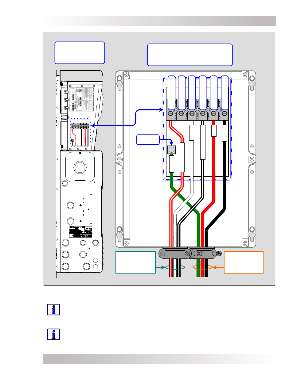
4.0 Wiring Diagrams
MS-PAE Series Inverter –
showing AC wires from the
internal AC wiring terminal
3
0
3
0
Left side view of
inverter mounted
on MP Enclosure
.
B
L
AC
K
.
RE
D
.
W
HIT
E
.
B
L
AC
K
w
/S
T
RIP
E
.
RE
D w
/S
T
RIP
E
.
G
RE
E
N
Inverter AC
Input Wires
(Leg 1 and 2)
Inverter AC
Output Wires
(Leg 1 and 2)
AC
GROUND
A
C
H
O
T
2
O
U
T
A
C
N
E
U
TR
A
L
A
C
N
E
U
TR
A
L
A
C
H
O
T
1
O
U
T
A
C
H
O
T
1
IN
A
C
H
O
T
2
IN
Figure 4-2, Inverter AC Input and Output Wiring Diagram - MS-PAE Series
Info: When wiring the MS-PAE Series inverter, only a single neutral wire (either an
inverter input or output neutral wire) is required to be connected to a AC NEUTRAL
busbar inside the MP enclosure. This is because the input and output neutral terminals
are connected together inside the MS-PAE Series inverter.
Info: The busbars labeled AC NEUTRAL in the MP enclosure ARE connected together,
so all neutral connections are in common with each other.