Magnum Energy Magnum Panel (MP Series) User Manual
Page 58
© 2011 Magnum Energy, Inc.
Page 51
3.0 Installation
3.8 Wiring Accessories
The NEC/CEC requires the insulation of all conductors inside the MP enclosure to be rated for the
highest voltage present. The MP enclosure is designed to work with inverters that provide 120/240V
AC (i.e., MS-PAE Series), therefore, the voltage rating of the communications cables inside the MP
enclosure must be rated for 300 volts or higher to be code compliant.
With the purchase of the MP enclosure, Magnum has included three six-foot, yellow communication
cables with 300-volt rated insulation. These communications cables — shown below — are provided
to make the connections between Magnum inverters and any accessories easier and code compliant.
Figure 3-27 shows a basic drawing for connecting accessories into and out of the MP enclosure.
Refer to Section 4.0 for specifi c communications wiring diagrams for your particular MP enclosure.
Info: These cables carry less than 30 volts and are thus considered a “limited energy
circuit”, which is normally not required to be installed in conduit.
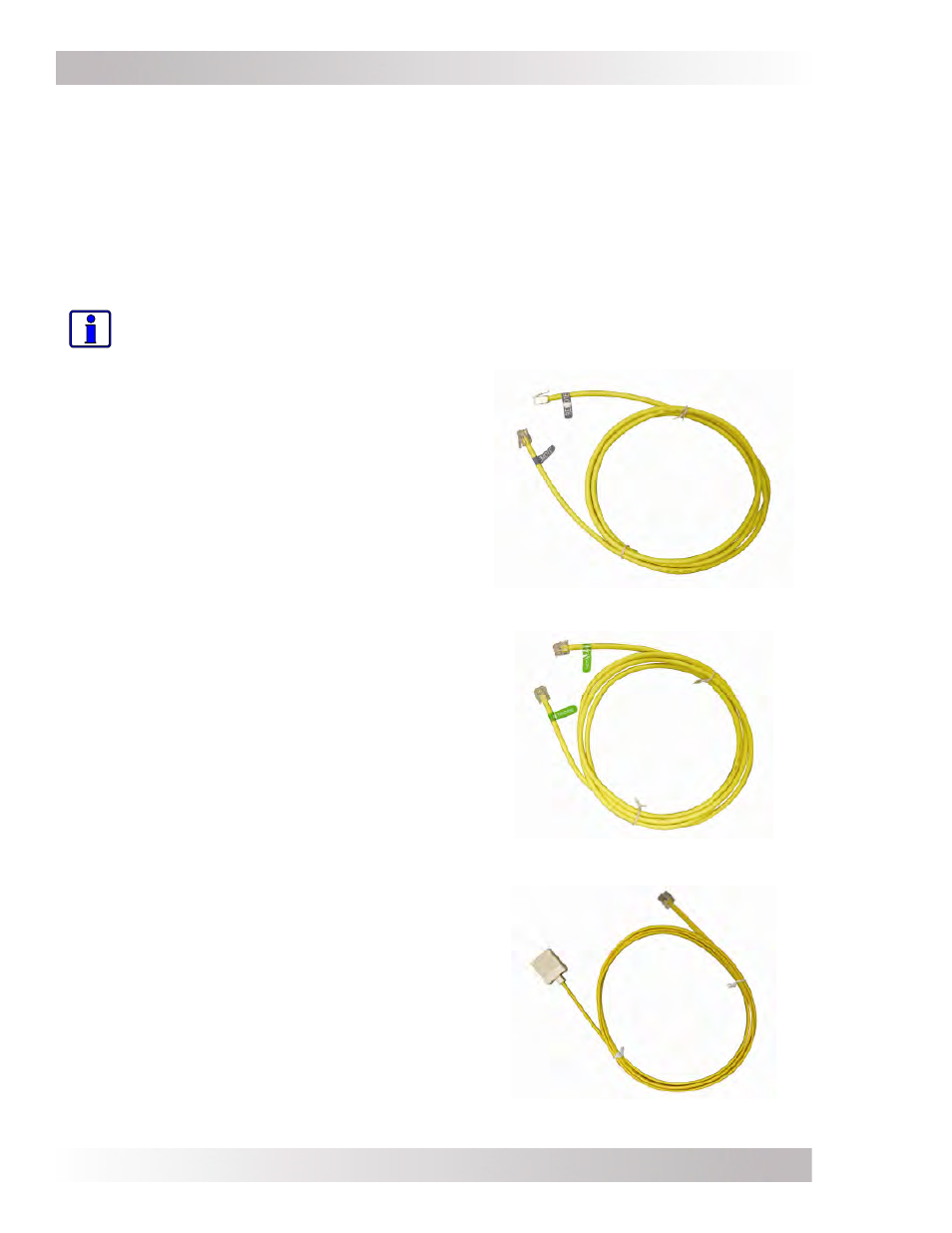
Figure 3-24 shows the ‘REMOTE’ cable. It allows
a remote control — such as the ME-RC (Remote
Control), ME-ARC (Advance Remote Control), or
ME-RTR (Router) — to be connected to the inverter
through the MP enclosure. This cable is a 6’ (1.83 m),
4-conductor, telephone-type cable with a RJ14 (m)
connector and a blue REMOTE label on each end. One
end of this cable is connected to the remote, and the
other end is routed inside the MP enclosure and then
connected to the inverter’s REMOTE port.
Figure 3-24, REMOTE Communication Cable (300V Rated)
Figure 3-25 shows the ‘NETWORK’ cable. It allows
Magnum accessories — like the ME-AGS-N (Auto
Generator Start - Network) or ME-BMK-NS (Battery
Monitor - No Shunt) — to be connected to the inverter
through the MP enclosure. This cable is a 6’ (1.83
m), 4-conductor, telephone-type with a RJ14 (m)
connector and a green NETWORK label on each end.
One end of this cable is connected to the accessory,
and the other end is routed inside the MP enclosure
and then connected to the inverter’s NETWORK port.
Figure 3-25, NETWORK Communication Cable (300V Rated)
Figure 3-26 shows the ‘EXTENSION’ cable. It allows
the Magnum Battery Temperature Sensor (BTS) to be
connected to the inverter through the MP enclosure.
This is a 6’ (1.83 m), 4-conductor, telephone-type
cable with a RJ14 (m) connector on one end and
a RJ14 (f) plug on the opposite end. The female
plug connects to the ME-BTS (Battery Temperature
Sensor). After connecting to the ME-BTS, this
extension cable is routed inside the MP enclosure and
connects to the inverter’s BTS port.
Figure 3-26, Extension Cable (300V Rated)