Magnum Energy Magnum Panel (MP Series) User Manual
Page 44
© 2011 Magnum Energy, Inc.
Page 37
3.0 Installation
3.5.3
Wire Routing
Before connecting any wires, determine all wire routes to and from the MP enclosure/inverter.
Typical routing scenarios are:
•
AC input wiring from the main AC panel or from a generator to the MP enclosure
•
AC input and output from the MP enclosure to the inverter
•
DC wiring from the batteries to the MP enclosure
•
DC wiring from the inverter to the MP enclosure
•
AC output wiring from the MP enclosure to the AC sub-panel or to dedicated circuits
•
Battery Temperature Sensor cable from the inverter to the batteries
•
Remote control and stacking cables to the inverter through the MP enclosure
•
Ground wiring to and from the MP enclosure
3.5.4
Grounding
The MP/Inverter system is intended to be installed as part of a permanently grounded electrical
system per the National Electrical Code (NEC) ANSI/NFPA 70 in the United States, Canadian Electrical
Code (CEC) CSA 22.1 in Canada, as well as all state and local code requirements. Information
and diagrams on the AC and DC ground circuits between the inverter and the MP enclosure are
provided in the AC and DC wiring sections.
Information on grounding the entire MP/inverter system to earth ground is provided in Section
3-11 and the actual system ground wiring confi guration must be determined by the installer.
3.5.5
Torque Requirements
Follow the specifi c torque recommendations in the tables below to ensure your fasteners are tightened
suffi ciently. To ensure your connections are correct, you should use an accurate, quality torque wrench.
CAUTION: It is highly recommended to go back over all fasteners/connections and re-
torque after 5 days, and every 6 months thereafter.
CAUTION: AC and DC power/wire connections that are under-torqued could become
loose and result in a fi re hazard. On the other hand, over-tightening a bolt could cause
the fastener to be snapped off.
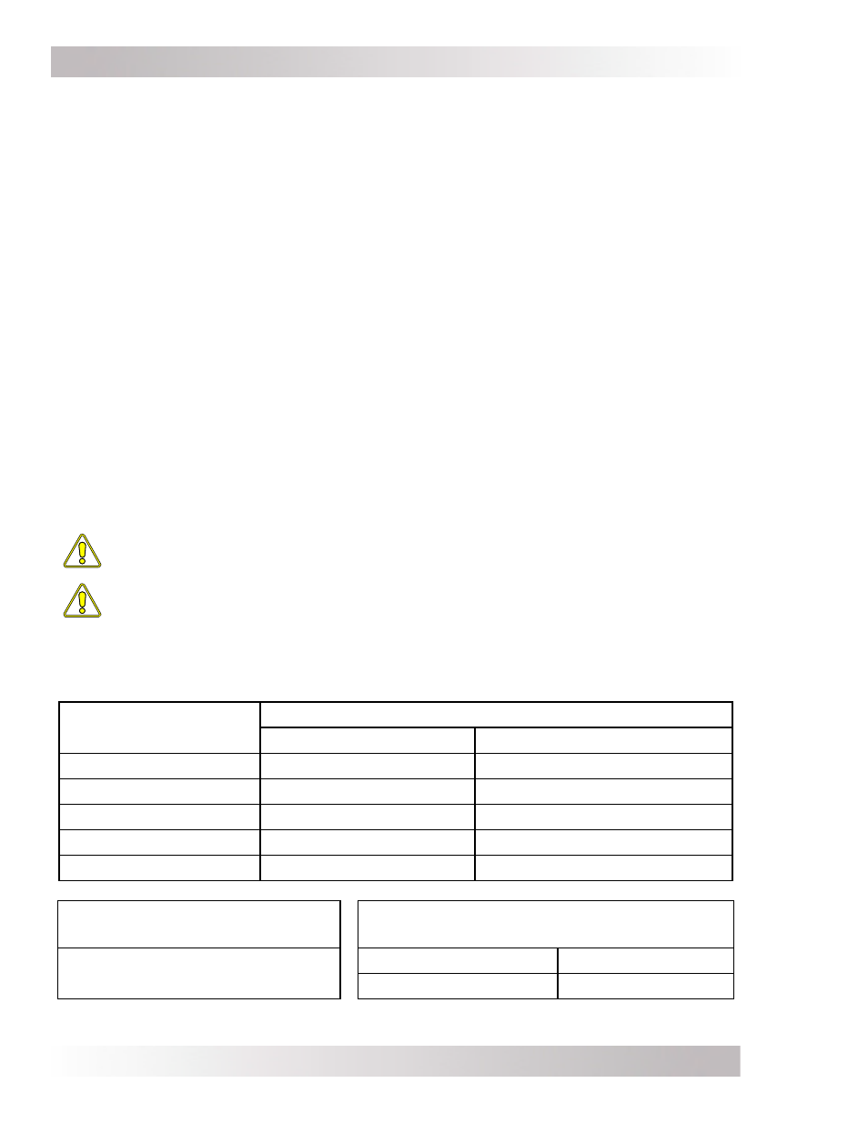
Table 3-1, Torque Values for Dual Hole Busbars
Torque values for the dual hole busbars (i.e., AC, DC, AC NEUTRAL and GROUND busbars) -
these busbars have different torque values for the small and large set-screws.
Wire Size
Busbar Set-Screw Size Torque Values
10-32 (Small Set-Screw)
5/16-24 (Large Set-Screw)
#14 to #10 AWG
15 in. lbs. (1.7 N-m)
35 in. lbs. (4.0 N-m)
#8 AWG
20 in. lbs. (2.3 N-m)
40 in. lbs. (4.5 N-m)
#6 AWG
25 in. lbs. (2.8 N-m)
45 in. lbs. (5.1 N-m)
#4 AWG
Not Applicable
45 in. lbs. (5.1 N-m)
#3 to #1/0 AWG
Not Applicable
50 in. lbs. (5.6 N-m)
Table 3-2, Torque Values for
3/8-16 Bolts
1
Table 3-3, Torque Values for Terminal
Screws on AC Input Breakers
10 to 12 ft. lbs.
(13.6 to 16.3 N-m)
Single-pole 60A breakers
45 in. lbs. (5.1 N-m)
Double-pole 30A breakers
45 in. lbs. (5.1 N-m)
Note 1 - The 3/8-16 bolts are used on the DC Shunt Busbars and DC Disconnect Breakers.