Magnum Energy Magnum Panel (MP Series) User Manual
Page 65
Page 58
© 2011 Magnum Energy, Inc.
3.0 Installation
3.11.2
Equipment Grounding Conductor
The MP enclosure and all other non-current carrying exposed metal surfaces in the entire electrical
system that may be accidentally energized must be grounded. The equipment-grounding conductor
must be sized to safely carry the maximum ground-fault current likely to be imposed on it from
where a ground-fault may occur.
AC Side - When the inverter’s AC input circuit breaker provided in the MP enclosure is being
used as the inverter’s AC overcurrent protection device, the AC Equipment Grounding Conductor
(EGC–AC) for the inverter is based on the AC breaker size provided (#10 AWG for all MP models).
Connect the AC equipment-grounding conductor from the inverter’s AC ground connection to the
AC Ground Busbar (GBB) in the MP enclosure (Item 25 in Figure 2-7 or 2-8, Item 22 in Figure
2-9, or Item 16 in Figure 2-10a - depending on your MP model).
DC Side - When the DC circuit breaker provided in the MP enclosure is being used as the inverter’s
DC overcurrent protection device, the DC Equipment Grounding Conductor (EGC–DC) for the
inverter should be #4 AWG, which is based on the 250 amp DC breaker size provided. Connect the
DC equipment-grounding conductor from the inverter’s DC ground connection to the DC Ground
Busbar (GBB) in the MP enclosure (Item 27 in Figures 2-7 or 2-8, Item 25 in Figure 2-9, or Item
26 in Figure 2-10b - depending on your MP model).
If you are using AC or DC overcurrent protection that is different than that provided in the MP
enclosure or installing optional DC breakers inside the MP enclosure, in accordance with the NEC/
CEC you must determine your equipment-grounding conductors based on the ampere rating of
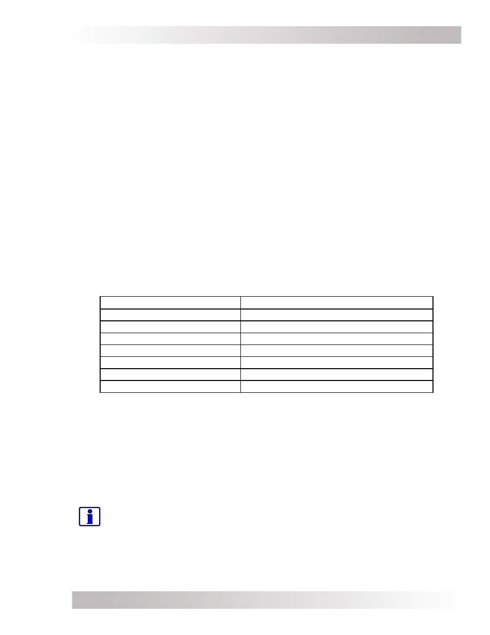
the overcurrent device protecting the circuit conductors. Use Table 3-7 to help determine the
equipment-grounding conductor. If the circuit conductors are oversized to compensate for voltage
drop, the equipment-grounding conductor must also be oversized proportionally.
Table 3-7, Equipment Grounding Conductor Sizing
Rating of Overcurrent Device
Minimum Size of Copper Ground Wire
15 amp
#14 AWG
20 amp
#12 AWG
30 - 60 amp
#10 AWG
100 amp
#8 AWG
200 amp
#6 AWG
300 amp
#4 AWG
400 amp
#3 AWG
3.11.3
System Bonding Jumper
The MP enclosure provides the
single
point of ground [System Bonding Jumper (SBJ)] for the AC
and DC system. If the MP enclosure is the central connection point for all ground wiring (usually
in an off-grid system) and there is no other connection to ground from neutral (in the AC system)
or negative (in the DC system), then leave the ground bond connections in place. Remove any
other neutral to ground connection in the AC system, such as in other electrical sub-panels; or,
any negative to ground connection in the DC system.
For utility connected systems where the neutral and ground are already bonded in the main utility
circuit breaker box (AC distribution panel), the NEUTRAL-GROUND wire MUST BE REMOVED from
the MP enclosure. See Section 3.9 to remove this neutral to ground connection.
Info: Inverters and portable generators that have electrical outlets usually have the
neutral and ground bonded internally. These types of devices are not recommended
to be connected to the MP/inverter system as they would fi rst need to be modifi ed to
separate the neutral and ground bonding internally.
For systems or devices that connect the DC negative to ground independently (i.e., separate DC
main electrical distribution panel or PV-GFP device), the NEGATIVE-GROUND busbar (Item 27 in
Figure 2-9, or Item 29 in Figures 2-7, 2-8 and 2-10b - depending on your MP model) MUST BE
REMOVED inside the MP enclosure. See Section 3.10 to remove this negative to ground connection.