Whelen 90033 User Manual
Fig.1
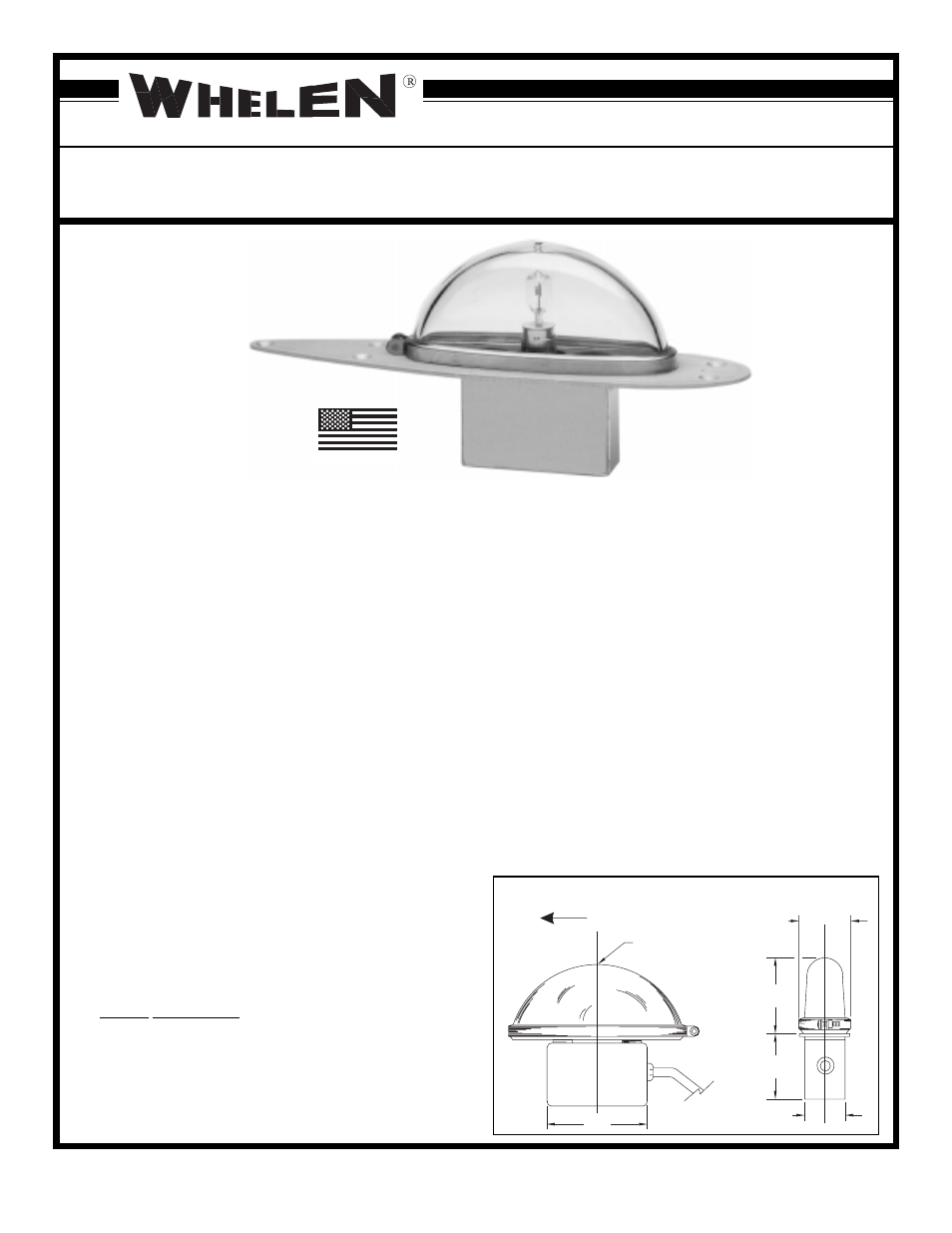
LC
1.95
(REF)
2.35
(REF)
.90
(REF)
1.65
(REF)
.125 DRAIN HOLE
(LOWER MOUNTS)
2.90
FWD
LC
90033 - ( ) FLASHING ANTI-COLLISION LIGHT ASSEMBLY
OPERATING INSTRUCTIONS.
Nominal Operational Voltage: 27.5 VDC
Average Input Current:
3.2 AMPS
Lamp for all Units:
28VDC, 150 Watts Max.
EQUIPMENT LIMITATIONS
An approved anti-collision system consists of two lights, one
located on the top of the vertical fin, and one located on the
underside of the fuselage.
INSTALLATION PROCEDURES: The following information is to
assist you in installing a Whelen flashing anti-collision light system.
1)
Choose the appropriate Model 90033 - ( ) replacement light
assembly which is applicable to your aircraft.
2)
The installation procedure described in the following text will
be confined to a single light installation, but is identical for
multiple light installation if required.
3)
Remove old anti-collision light, locate and save existing +28
VDC lead and (-) ground leads. Clean and prep lead ends as
required.
4)
Use existing mounting holes and hardware.
NOTE: If a special mounting adapter plate is required, contact
Whelen Aviation Division for requirements.
5)
Connect existing +28 VDC lead to the white lead on the light
assembly and connect existing (-) ground lead to the black
lead on the light assembly. Both leads must be connected by
an approved aircraft connection.
6)
Breaker Requirements
Make sure existing system is equipped with an appropriate
sized breaker.
7)
Install light assembly and insure that all leads are clear of any
©1997 Whelen Engineering Company Inc.
Form No.13223B (092199)
ENGINEERING COMPANY INC.
ROUTE 145, WINTHROP ROAD
CHESTER, CONNECTICUT 06412-0684
TELEPHONE: (860) 526-9504
FAX: (860) 526-4078
obstructions and ty-rap as required. Secure light assembly,
use lock washers and/or thread lock, on all threaded fas-
teners.
8)
Check all avionics systems for interference from this instal-
lation.
9)
A flight check should be performed by a properly certified
pilot.
10) When necessary, waterproof the flasher base assembly to
aircraft. Apply single part silicone (RTV) or equivalent
around any open area where water could get in.
11) Update aircraft records and complete Form 337.
12) Obtain FAA field approval for installation.
LAMP REPLACEMENT PROCEDURE
1)
Remove clamp ring and lens. Remove old lamp.
2)
Install new lamp. Wipe new lamp thoroughly.
3)
Install lens and clamp ring. Confirm that the clamp ring and
screw are oriented as shown in Fig. 1.
Installation Guide for Model 90033 - ( )
Flashing Anti-Collision Light Assembly
TSO-C96a
APPROVED
MADE IN THE U.S.A.
Fig.1