Whelen 7145750 User Manual
Aviation, Engineering company inc
Page 1
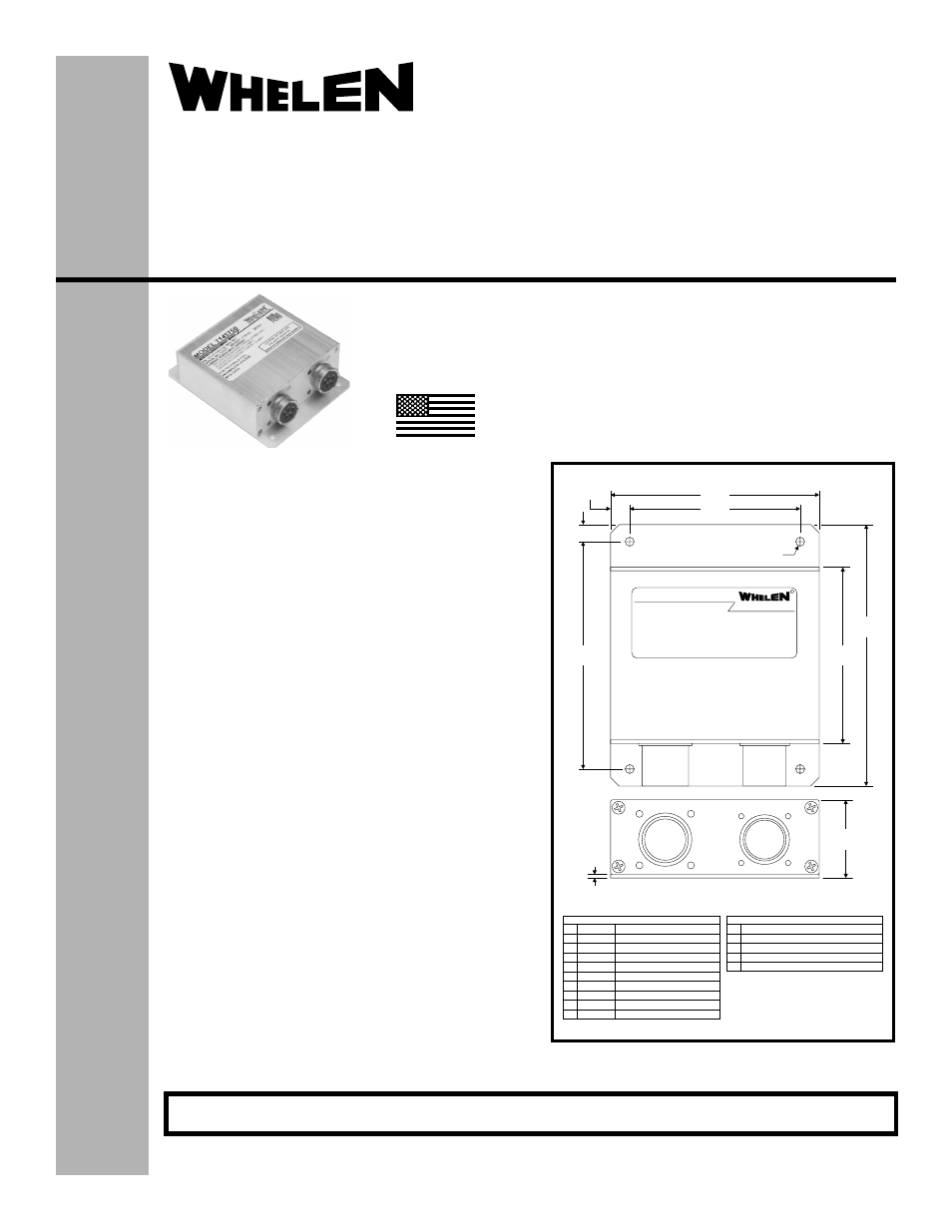
4X .Ø156
CHESTER, CONNECTICUT 06412-0684
ENGINEERING COMPANY, INC.
BY:
R
MODEL 7145750
3.67
3.00
.335
.30
4.00
3.10
4.60
J1
INPUT
J2
INPUT
1.38
.062
J2
J1
A AC1
J2 MS27508E12F98S
B AC2
Anti-Collision Light
Anti-Collision Light
C AC3
Anti-Collision Light
D AC4
Anti-Collision Light
E V+
V IN
F AC5
Anti-Collision Light
J
K
Cathode
V+
IR Light
V IN
G AC6
Anti-Collision Light
H Cathode FWD & AFT Position Lights
A +28V Anti-Collision Light
B Ground
C SYNC
D +28V Position Light
E +28V IR Light
J1 MS27508E10F5P
Model:7145750
®
ENGINEERING COMPANY INC.
Aviation
Installation Guide:
Aviation model 7145750
P/N 01-0771457-50
Flasher/Current Source
©2010 Whelen Engineering Company Inc.
Form No.14418 (092710)
For warranty information regarding this product, visit www.whelen.com/warranty
SPECIFICATIONS:
Nominal Operational Voltage:............................................ 28 VDC
(Operation from 22-32 VDC)
Input Current (with 905695x Lighthead):
LED Position Light .......................................................... 0.23 Amps
LED Anti-Collision Light ([email protected] Sec.) ................... 3.9 Amps
LED Anti-Collision Light (Avg.) ...................................... 0.73 Amps
LED I.R. Light ([email protected] Sec.) ..................................... 0.3 Amps
LED I.R. Light (Avg.) ........................................................ 0.06 Amps
Flashrate.............................................................................. 45 ±5 Per. Min.
EQUIPMENT LIMITATIONS:
An approved Anti-Collision / Position Lighting System consists of at
least 2 flasher/current source units, each connected to a LED anti-
collision, position and infrared light lighthead.
Note: Due to circuitry relationship, the anti-collision and I.R. lights
cannot both be on at the same time.
The Infrared Light is a non-TSO function.
Certain types of installations may require additional testing.
CONTINUED AIRWORTHINESS:
If any bank of LEDs fail, the lighthead module should be checked. If
the module checks good, replace the flasher.
Note: An anti-collision light will automatically shut-off after 9-10
flashes if a failure is detected.
INSTALLATION PROCEDURES:
1.
Consider areas or locations designated by the aircraft
manufacturer. Check that breakers are properly rated.
2.
Attach the flasher using the (4) 0.156 dia. mounting holes.
3.
Connect the inputs according to the chart shown. Connections
to be in accordance with FAA approved methods.
4.
Check all avionic systems for interference from the installation
5.
A flight check should be performed by a certified pilot
6.
Update aircraft records, complete form 337 and obtain FAA
field approval for installation, as necessary
MADE IN THE U.S.A.
The conditions and tests required for TSO approval of this
article are minimum performance standards. It is the
responsibility of those installing this article either on or
within a specific type or class of aircraft to determine that
the aircraft installation conditions are within the TSO
standards. TSO articles must have separate approval for
installation in aircraft. The article may be installed only if
performed under 14 CFR part 43 or the applicable
airworthiness requirements.
TSO-C30c
TYPES I, II & III /
TSO-C96a
CLASS II
APPROVED
51 Winthrop Road
Chester, Connecticut 06412-0684
Phone: (860) 526-9504
Fax: (860) 526-2009
Internet: www.whelen.com
Sales/Service e-mail: [email protected]
- 7145751 7118400 7118401 7108040 7117001 7117002 7117007 7117008 7117009 7117010 7108019 9027701 9027702 7105000 7105001 7105010 7105011 9052008 9052018 7145700 7123405 7114800 7114801 7123404 7112000 7123402 OR6502GE OR6502RE 9061001 9061002 OR6501GE OR6501RE 7105500 7155401 7155402 7108004 7108014 9061351 9061352 7108001 7108006 7145701