Whelen 90044 User Manual
Aviation, Engineering company inc
Page 1
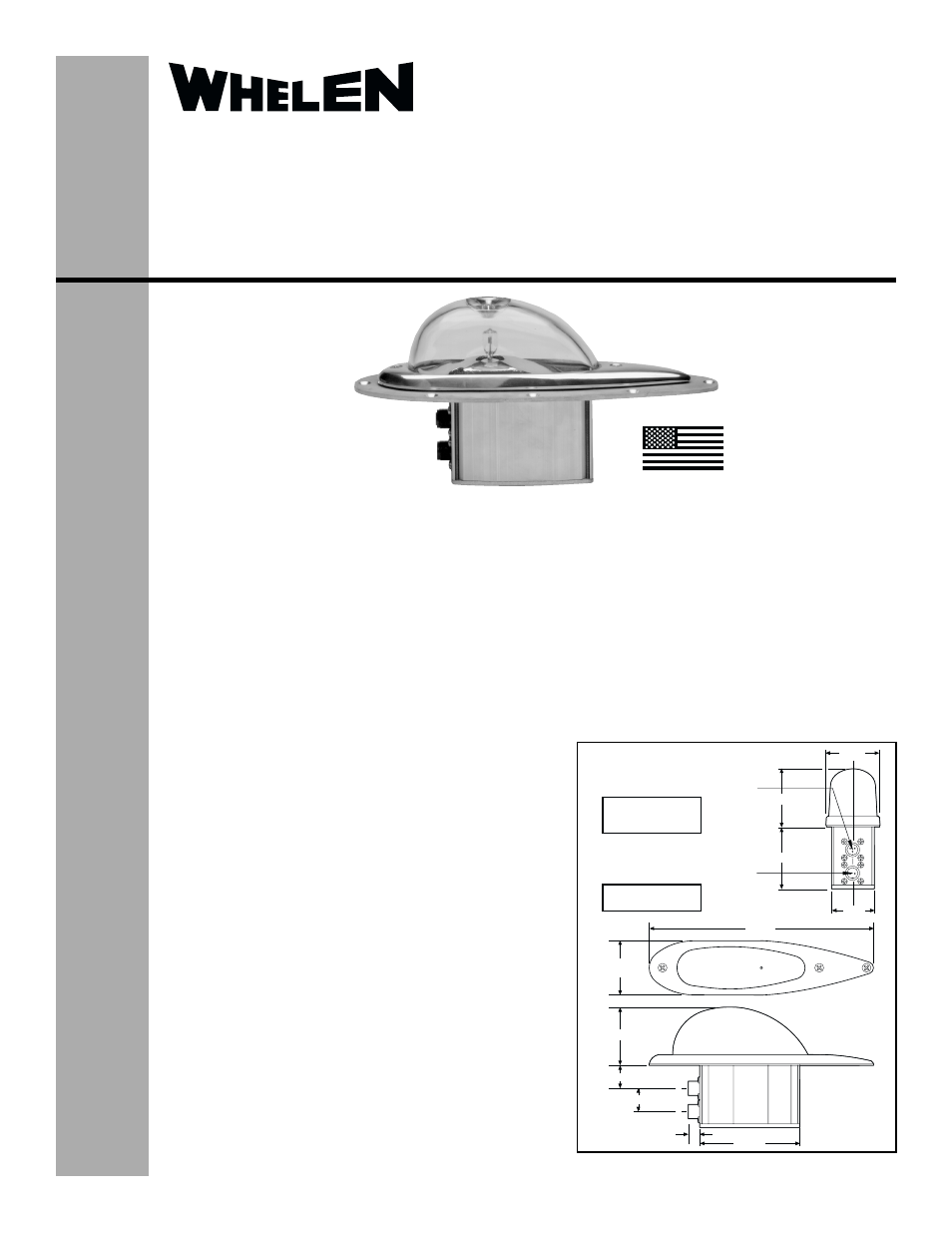
2.38"
2.70"
2.82"
1.88"
9.87"
2.38"
1.00"
.50"
4.40"
.93"
2.70"
*OUTPUT
Receptacle MS 3102R10SL-3S mates
with MS 3106F10SL-3P or equivalent.
POS. A, SW. GND.
POS. B, POWER OUT
POS. C, N/C.
INPUT, 28 VDC.
Receptacle MS 3102R10SL-4P mates
with MS 3106F10SL-4S or equivalent.
*Only used if
slave is used.
POS. A, (+) 28 VDC.
POS. B, (-) GROUND.
®
ENGINEERING COMPANY INC.
Route 145, Winthrop Road,
Chester, Connecticut 06412
Phone: (860) 526-9504
Fax: (860) 526-2009
Internet: www.whelen.com
Sales/Service e-mail: [email protected]
Aviation
Installation Guide
Model 90044 - ( )
Flashing Anti-Collision Light Assembly
©1998 Whelen Engineering Company Inc.
Form No.13224C (062706)
OPERATING INSTRUCTIONS:
Operational Voltage: . . . . . . . . .28 VDC
Average Input Current: . . . . . . .Master 3.2 Amps
Master/Slave 6.5 Amps
EQUIPMENT LIMITATIONS: An approved anti-collision system
consists of two lights, one located on the top of the vertical fin,
and one located on the underside of the fuselage.
INSTALLATION PROCEDURES: The following information is to
assist you in installing a Whelen flashing anti-collision light
system.
1.
Choose the appropriate Model 90044- ( ) replacement light
assembly which is most applicable to your aircraft.
2.
The installation procedure described in the following text will
be confined to a single light installation, but is identical for
multiple light installation if required.
3.
Remove old anti-collision light, locate and save existing +28
VDC lead and (-) ground leads. Clean and prep lead ends
as required.
4.
Use existing mounting holes and hardware.
NOTE: If a special mounting adapter plate is required, contact:
Whelen Aviation Division for requirements.
5.
Connect the existing +28 VDC lead to the white/blue lead on
the input cable assembly (supplied with light assembly).
Then connect the existing ground lead to the white wire on
the input cable assembly. If a shield wire exists on the
aircraft, connect it to the shield wire assembly. If no shield
wire exists on the aircraft, trim the shield wire on the cable
assembly flush with the cable jacket. Both leads must be
connected by an FAA approved connection.
6.
Make sure the existing system is equipped with an
appropriate sized breaker.
7.
Install light assembly and insure that all leads are clear of
any obstructions and ty-rap as required. Secure light
assembly, use lock washers and/or thread lock on
all threaded fasteners.
8.
Check all avionics systems for interference from
this installation.
9.
A flight check should be performed by a properly
certified pilot.
10. When necessary, waterproof the flasher base
assembly to aircraft. Apply single part silicone
(RTV) or equivalent around any open area where
water could get in.
11. Update aircraft records, complete Form 337 and
obtain FAA field approval for installation.
TSO-C96a
APPROVED
MADE IN THE U.S.A.