Whelen Cessna Citation 550 User Manual
Aviation, Engineering company inc
Page 1
Wingtip Power Supply Replacement for
Cessna Citation 550, Serial #128 and above,
S550 and 560 serial #0001-0256 without
SB560-3308 applied, with 90159 Series
Wingtip Strobe Light Assembly.
®
ENGINEERING COMPANY INC.
Route 145, Winthrop Road,
Chester, Connecticut 06412
Phone: (860) 526-9504
Fax: (860) 526-2009
Internet: www.whelen.com
Sales/Service e-mail: [email protected]
Aviation
©1997 Whelen Engineering Company Inc.
Form No.13048C (052102)
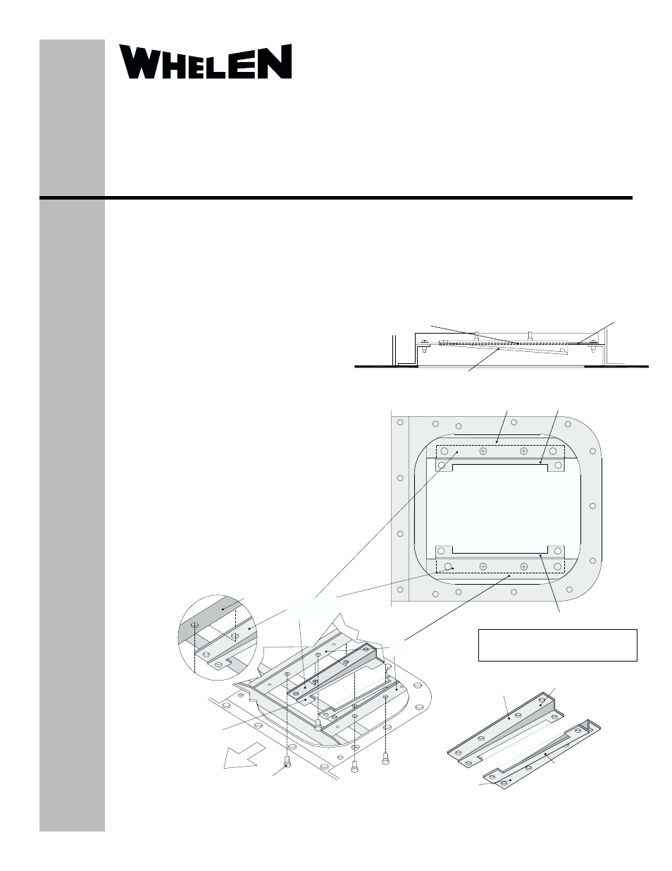
MOUNTING BRACKET LIPS
ON TOP OF EXISTING
BRACKETS
EXISTING
BRACKET
MOUNT. BRACKETS “A” & “B” TO SLOPE UPWARD FACING OUTBOARD OF AIRCRAFT WING
VIEW A-A
NOTE: ACCESS CUT-OUT SHOWN IN
ISOMETRIC DRAWINGS AS SEEN FROM
BELOW THE AIRCRAFT’S WING
EXISTING
BRACKET
EXISTING MOUNTING SCREWS (QTY. 4) TO SECURE
MOUNTING BRACKETS TO EXISTING BRACKETS
MOUNTING BRACKETS “A”
AND “B” ARE TO SLOPE
UPWARD FACING OUTBOARD
OF AIRCRAFT WING
OU
TB
OAR
D
MOUNTING BRACKET “B”
MOUNTING BRACKET “A”
OUTBOARD
INBOARD
EXISTING BRACKET
MOUNTING BRACKET “B”
PN / 11-170576-000
MOUNTING BRACKET “A”
PN / 11-170575-000
BRACKET LIP
BRACKET LIP
EXISTING
BRACKET
MOUNTING BRACKET
LIPS ON TOP OF EXISTING
BRACKETS
90101 Series Strobe Light Power Supply
Installation . . .
1.
On both wings of the aircraft, remove the
wingtip access panel by unscrewing the
mounting screws.
2.
Remove existing strobe light power supply
from the wing-tip access cut-out by removing
the four mounting screws. Disconnect cables
from power supply.
3.
Install the two supplied mounting brackets
(“A” and “B”) with lips on top of existing
brackets, located inside wing-tip access cut-
out, and secure with the four mounting
screws.
IMPORTANT NOTE: When brackets are
installed, insure that the upward slope is
facing outboard of the wing.
4.
Connect the Whelen Strobe Light Power
Supply to the connectors of the existing
cables and install the power supply onto “A”
and “B” mounting brackets with the
connectors facing outboard. Secure the
power supply with the four #8-32 MS51957-
46mounting screws (supplied) to the “A” and
“B” mounting brackets.
5.
Replace the wingtip access panel over the
wingtip cut-out, and secure with the mounting
screws.