Whelen HDACF User Manual
Aviation, Fig. 1 fig. 2, Specifications
Page 1
®
ENGINEERING COMPANY INC.
Route 145, Winthrop Road,
Chester, Connecticut 06412
Phone: (860) 526-9504
Fax: (860) 526-2009
Internet: www.whelen.com
Sales/Service e-mail: [email protected]
Aviation
Installation Guide:
Model HDACF
Strobe Power Supply Assembly
FAA/PMA Approved.
©2001 Whelen Engineering Company Inc.
Form No.13603A (030303)
Specifications
Model Number - HDACF
Part Number -
01-0770028-05
Current Draw - 7.0 Amps @ 14 Volts D.C.
3.5 Amps @ 28 Volts D.C.
Weight -
2.1 lbs.
Length -
5.50”
Height -
2.37”
Operation
This power supply will operate up to 3 strobe light head assemblies.
When operating two lights in the alternating mode, 42 joules of power are
produced for each light. While in simultaneous mode, power to each light
is 21 joules. When operating 3 lights, strobe outlet 1 produces 42 joules
of power and alternates with strobe outlets 2 & 3 (producing 21 joules
each) that flash simultaneously (see Fig. 1).
Location
1.
Consider areas or locations designated by the aircraft
manufacturer. Do not mount the strobe power supply
any closer than 3 feet from the ADF loop.
2.
For alternate locations, consider areas such as the
cabin baggage compartment, the floor under the seat,
non-structural bulkheads, firewalls etc.
3.
If necessary, fabricate support brackets or shelves, and
attach them to the aircraft structure to provide a
mounting surface that will withstand the inertia forces
stipulated in chapters 1 & 3 of AC 43.13-2A
4.
An “IA” or other representative of the FAA must approve
documentation of structural integrity of the fabricated
installation.
5.
When installing the strobe light power supply in an
inverted position, drill a 3/16” diameter hole in the
lowest corner of the cover to provide for moisture
drainage. Care must be taken not to let the drill protrude
into the power supply, for it will inflict damage to the
electronic components.
6.
Specifically call out the location of the strobe light power
supply on FAA form 337.
Wiring
WARNING: STROBE LIGHT POWER SUPPLIES ARE
POLARITY SENSITIVE. REVERSING THE INPUT POLAR-
ITY WILL CAUSE SEVERE DAMAGE TO THE POWER
SUPPLY.
Steps below: “Ref. AC 43.13-1B, Chapter 11, Sections
1,2,3, & 7”.
1.
Choosing wire size of A+ input lead, refer to Paragraph
444 “Electric Wire Chart” Figure 11.7 and 11.7A, with
reference to Strobe Light Model Current requirement
chart on page 6 and 11, and “Wire and Circuit
Protection Chart” Figure 11.1.
2.
Shielded wire is not generally necessary, but has
proven effective in reducing the possibility of radio
interference.
3.
The power supply shall acquire its power from a low
impedance source such as the alternator or generator
end of the electrical buss as close to the battery as
possible.
4.
For penetrating pressure hull, refer to the aircraft
service manual.
5.
Check all avionics systems for interference.
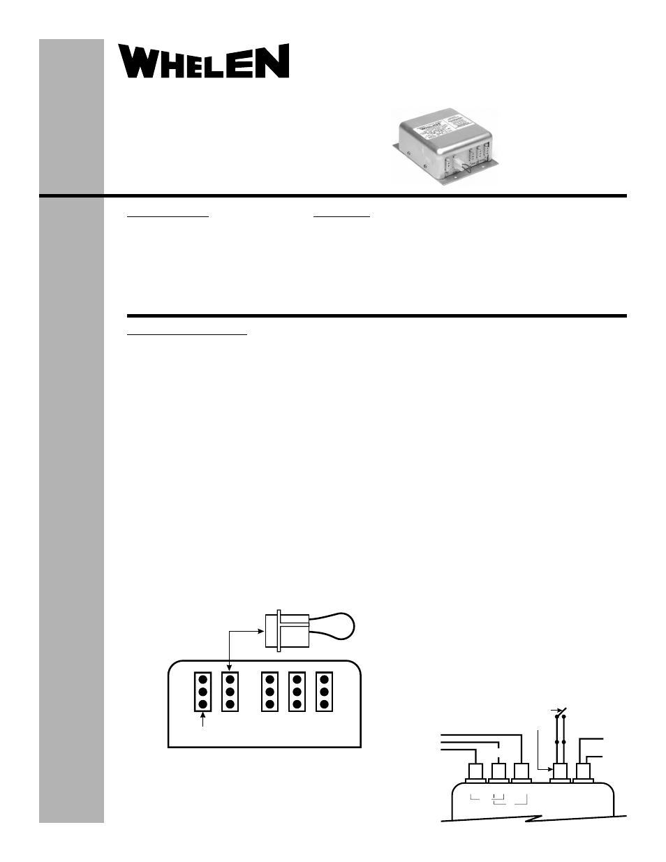
Trigger Function
Jumping pins 1 and 2 on the trigger plug will provide an
alternating flash pattern between strobe outlet 1 and strobe
outlet(s) 2 and/or 3. Installing a switch in series with the
jumper will allow strobe outlets 2 & 3 to be turned off, while
strobe outlet 1 remains on (see Fig. 2).
Installation Procedures
32
1
(1) +
Jumper to be inserted
in trigger selector outlet
Outlet
1
Outlet
2
Outlet
3
Connector for
input power cable
TYPICAL STROBE HOOK-UP
PIN 1 - RED - ANODE
PIN 2 - BLACK - CATHODE
PIN 3 - WHITE - TRIGGER
1 TYP.
2 TYP.
3 TYP.
(2) -
(3)N/C
STROBE OUTLETS
PIN
STROBE OUTLETS
TRIGGER
SELECTOR
OUTLET
POWER
IN
#1
#2
#3
14V or 28V
-
+
OFF
ON
Switch normally closed
1/10 amp rated
Jumper inserted into
trigger selector outlet
SYNC
ALT
Fig. 1
Fig. 2