Whelen 7096600 User Manual
Aviation, Engineering company inc
Page 1
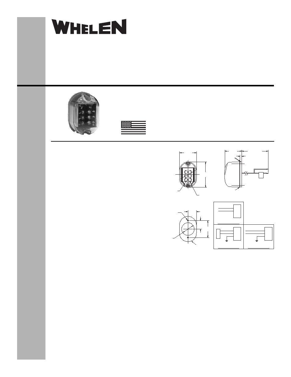
1.74
2.60
.870
CN1
(+28) WHITE
(+28) WHITE
(GND) BLACK
7096600 Wiring Diagram
7096601 Wiring Diagram
(GND) BLACK
(Chassis GND) BLACK
1
2
3
LED
Module
LED
Module
LED
Module
(+28) WHITE
7096602 Wiring Diagram
(GND) WHITE/BLUE
(Chassis GND) SHIELD
Ø1.30
.125 DIA. (2 places)
Clearance Hole
#4 Hardware
Light Ass’y
Recommended Mounting
Hole Pattern
.875
1.750
1.74
Top
.187
22.00 ±1.00
2XR.87
LED Array
(White )
7096600 Assembly
Shown For Reference
Slots To
Bottom
The conditions and tests required for TSO approval of this
article are minimum performance standards. It is the
responsibility of those installing this article either on or
within a specific type or class of aircraft to determine that
the aircraft installation conditions are within the TSO
standards. TSO articles must have separate approval for
installation in aircraft. The article may be installed only if
performed under 14 CFR part 43 or the applicable
airworthiness requirements.
®
ENGINEERING COMPANY INC.
Route 145, Winthrop Road,
Chester, Connecticut 06412
Phone: (860) 526-9504
Fax: (860) 526-2009
Internet: www.whelen.com
Sales/Service e-mail: [email protected]
Aviation
Installation Guide:
Models 7096600, 7096601, 7096602
P/N:01-0770966-00, 01-0770966-01,
01-0770966-02
LED Tail Position
Light Assembly
©2003 Whelen Engineering Company Inc.
Form No.13876D (031507)
TSO-C30c
TYPE III
APPROVED
MADE IN THE U.S.A.
OPERATING INSTRUCTIONS:
Nominal Voltage: . . . . . . . . . . . .28 VDC
Operational Voltages: . . . . . . . .24 - 30 VDC
Input Current:. . . . . . . . . . . . . . .0.30 Amps
EQUIPMENT LIMITATIONS: The approved tail position
light assembly should be mounted vertically and as far aft
on the aircraft as possible, on a thermally conductive
surface
CONTINUED AIRWORTHINESS: The LED tail position
light assembly is designed with 6 LED’s. If any one LED
fails, the unit must be repaired or replaced.
INSTALLATION PROCEDURES: The following
information is to assist you in installing a Whelen tail
position light.
1.
Choose the appropriate model light assembly which
is most applicable to your aircraft.
2.
Remove the old light, locate and save the existing
+28VDC lead and (-) ground lead. Clean and prep
ends as required.
3.
Use the existing mounting holes and hardware.
Note: If a special adaptor plate is required, contact
Whelen Aviation Division for requirements.
4.
Connect the existing +28 VDC lead to the white 20
AWG lead on the input cable assembly (supplied with
light assembly). Connect the existing ground lead to
the black or white/blue 20 AWG wire on the input
cable assembly. If a chassis ground wire exists on the
aircraft, connect it to the chassis ground wire
assembly. Both leads must be connected by FAA
approved techniques using approved hardware.
5.
Make sure the existing system is equipped with an
appropriate sized breaker.
6.
Remove two #4-40 screws from tail light assembly.
Save these screws.
7.
Install the light assembly and insure that all the leads are clear
of any obstructions and ty-wrap as required. Secure light
assembly using approved vibration resistant hardware methods.
Note “Top” marking on the unit.
8.
Re-mount the lens onto the assembly. Attach lens with
mounting screws (provided). NOTE: These screws feature a
nylon thread locking patch.
9.
Check all avionics systems for interference from this installation.
10. When waterproofing the assembly to the aircraft, apply aviation-
approved single part silicone (RTV) or equivalent around the
periphery with caution. Do not fill the drain holes at bottom of
unit. RTV should never be used between the rear surface of
the light assembly and its mounting surface.
11. Update aircraft records, complete Form 337 and obtain FAA
field approval for installation.