Whelen 7118201 User Manual
Aviation
Page 1
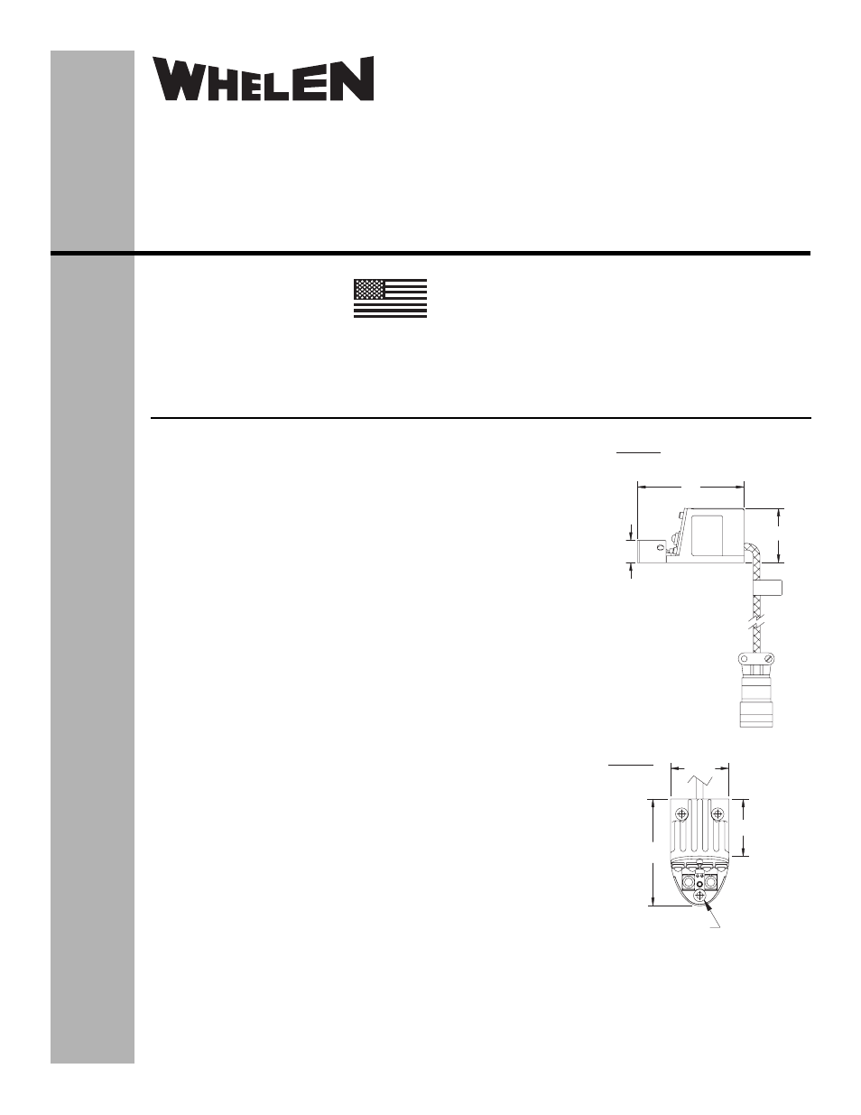
3 x 0.150 THRU
(countersink .281” dia. x 100°)
Pos. A - (+) 28 VDC
Pos. B - (-) Ground
Model(s):
7118201 (Green)
7118202 (Red)
Model(s):
7118201
7118202
0.50
2.41
1.23
1.32
1.30
2.41
The conditions and tests required for TSO approval of this
article are minimum performance standards. It is the
responsibility of those installing this article either on or
within a specific type or class of aircraft to determine that
the aircraft installation conditions are within the TSO
standards. TSO articles must have separate approval for
installation in aircraft. The article may be installed only if
performed under 14 CFR part 43 or the applicable
airworthiness requirements.
®
ENGINEERING COMPANY INC.
51 Winthrop Road
Chester, Connecticut 06412-0684
Phone: (860) 526-9504
Fax: (860) 526-2009
Internet: www.whelen.com
Sales/Service e-mail: [email protected]
Aviation
Installation Guide: 71182( )-series
Model(s) 7118201, 7118202
P/N(s): 01-0771182-01
01-0771182-02
LED Forward Position
Light Assembly
©2009 Whelen Engineering Company Inc.
Form No.14295 (051309)
TSO-C30c
TYPES I & II
APPROVED
MADE IN THE U.S.A.
OPERATING INSTRUCTIONS:
Nominal Operational Voltage: . . . 28 VDC (nominal)
Input Current: . . . . . . . . . . . . . . . . 0.32 Amps
Weight . . . . . . . . . . . . . . . . . . . . . . 0.25 lbs.
EQUIPMENT LIMITATIONS: An approved forward position lighting system
consists of two lights, one located on each wingtip, mounted behind a clear
lens.
CONTINUED AIRWORTHINESS: The 71182 series LED wingtip position
light assembly is designed with 6 LED’s. If any one LED fails, the unit must
be repaired or replaced.
INSTALLATION PROCEDURES: The following information is to assist in the
installation of a Whelen LED forward position light system.
1.
Choose the appropriate 71182( ) series light assembly.
2.
The installation procedure described in the following text will be
confined to a single light installation, but is identical for multiple light
installations.
3.
Make sure the system is equipped with an appropriate sized breaker.
Connect the +28VDC lead to position A on the input cable assembly
(supplied with the light assembly). Connect the existing ground lead to
position B wire on the input cable assembly or use the supplied
connector as shown in the illustrations. Both leads must be connected
by an approved FAA connection. Insure that the wire leads clear of any
obstructions and ty-wrap as required.
4.
Position the base of the new light assembly onto the mounting surface.
Insert three (3) #6 x 100° flat head screws into the mounting holes and
tighten firmly.
5.
Check all avionics systems for interference from the installation.
6.
A flight check should be performed by a properly certified pilot.
7.
Update aircraft records, complete Form 337 and obtain FAA field
approval for installation, as required.