Whelen A600PG/PR Series User Manual
Aviation, Specifications, Engineering company inc
Page 1
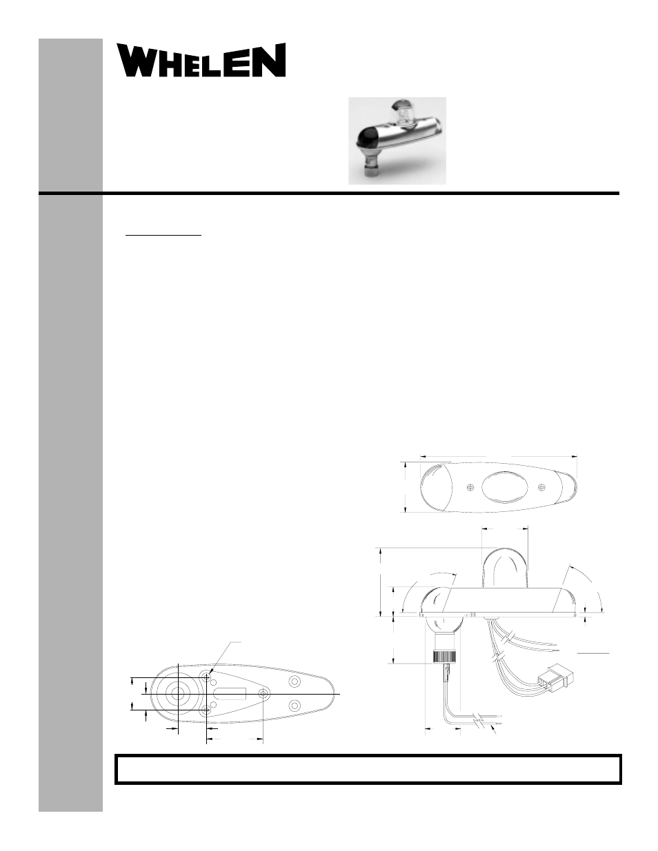
18 AWG TEFLON
1.79
110°
70°
1.08
.15
1.35
DIA.
1.66
RED(+14or +28VDC)
BLACK(-)GROUND
POS 1 - RED(ANODE)
POS 2 - BLACK(CATHODE)
POS 3 - WHITE(TRIGGER)
TAIL LIGHT WIRES(BLUE)
NO POLARITY
LEAD LENGTH 6.00"±1.00"
2.46
1.83
5.63
.50
1.00
.88
1.75
.140 DIA.
(3) MOUNTING HOLES
FOR #6-32 SCREWS
®
ENGINEERING COMPANY INC.
Aviation
Installation Guide
Model A600PG/PR Series
Wingtip Strobe
Anti-collision/Position
Light Assembly
©2001 Whelen Engineering Company Inc.
Form No.13609B (121410)
Specifications:
Position Lights -
Current Draw................ 4.0 Amps @ 14 Volts D.C.
2.0 Amps @ 28 Volts D.C.
Weight........................... 0.8 lbs.
Length........................... 5.6”
Width............................. 1.7”
Height ........................... 2.4”
INSTALLATION...
The A600 Series must be properly mounted to comply with FAR
Part 91.205(c-2) & (c-3). The light assembly must be mounted so
that the light distribution pattern is not obstructed by any parts of
the aircraft. A limited amount of obstruction is permitted (Ref. FAR
Part 23.1401 for anti-collision lights, and FAR 23.1387 for position
lights).
The baseplate must be mounted parallel to the vertical and
horizontal centerlines of the aircraft to project the patterns
properly.
MOUNTING...
1.
If necessary, fabricate the mounting pattern using
dimensions found in fig. 1.
2.
Make the necessary wiring connections using 18 gage wire
for the position lights, and Whelen 16 gage 3/c cable for the
strobe lights. All connections must use FAA approved
techniques.
3.
Remove the two (6-32 x .312) retainer mounting screws,
retainer and lens.
4.
Attach the base assembly to the wingtip using (3) #6-32
countersunk screws (unit may be sealed around periphery
with RTV or equivalent).
5.
Re-attach the lens and retainer.
WIRING...
1.
The strobe connector should plug into the Whelen interconnecting
cable, or a Whelen strobe power supply.
Observe the following strobe color coding:
PIN 1 - RED (Anode)
PIN 2 - BLACK (Cathode)
PIN 3 - WHITE (Trigger)
Caution:
When pins 1 & 2 or pins 2 & 3 are reversed, the system
will appear to operate normally, however this
condition will cause premature flash tube failure.
2.
Connect the forward position light wires as follows:
RED - +14 or +28 volts (depending on aircraft voltage)
BLACK - ( - ) Ground
3.
The tail position light has no polarity, as noted by both wires being
BLUE. Connect one BLUE wire to +14 or +28 volts (depending on
aircraft voltage). Connect the other BLUE wire to ground (see fig.
2)..
Fig. 1
Fig. 2
For warranty information regarding this product, visit www.whelen.com/warranty
51 Winthrop Road
Chester, Connecticut 06412-0684
Phone: (860) 526-9504
Fax: (860) 526-2009
Internet: www.whelen.com
Sales/Service e-mail: [email protected]
- 9045000 9036801 9036802 7108008 7108018 9056905 9056906 7155404 7155405 7155406 90340 series 7105500 7123404 7112000 7123402 7114800 7114801 OR6502GE OR6502RE 7118400 7118401 7108040 7117001 7117002 7117007 7117008 7117009 7117010 7108019 9027701 9027702 7105000 7105001 7105010 7105011 9052008 9052018 7145751 7106502 A650PG/PR Series 70239 Series