Whelen 9056901 User Manual
Aviation
Page 1
1
2
3
4
5
6
7
8
9
AC
AC2
AC3
AC4
AC5
C6
Cathode
1
V+
A
Cathode
Anti-Collision Light
Anti-Collision Light
Anti-Collision Light
Anti-Collision Light
V IN
Anti-Collision Light
Light
FWD & AFT Position Lights
Ground Recognition Light
Anti-Collision
CPC 206485 - 1
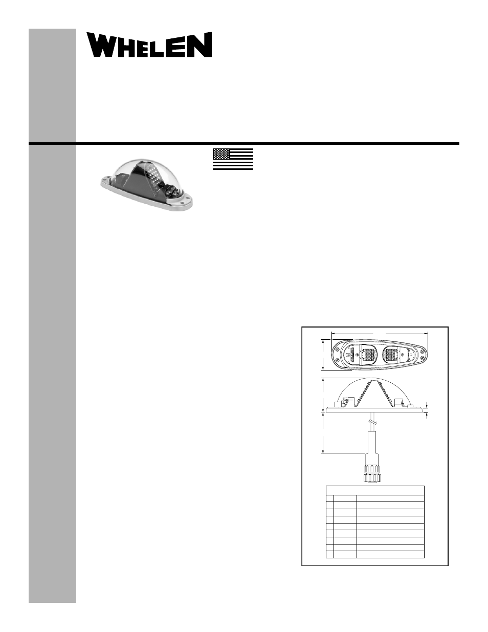
.25
2.01
12.0" ±1.0"
5.61
1.77
®
ENGINEERING COMPANY INC.
51 Winthrop Road
Chester, Connecticut 06412-0684
Phone: (860) 526-9504
Fax: (860) 526-2009
Internet: www.whelen.com
Sales/Service e-mail: [email protected]
Aviation
Installation Guide:
Aviation model 9056901, 9056902
P/N 01-0790569-01, 01-0790569-02
LED Position, Anti-Collision and
Ground Recognition Light Assembly
©2010 Whelen Engineering Company Inc.
Form No.14416 (092710)
EQUIPMENT LIMITATIONS:
An approved lighting system consists of two lights, one
located on each wingtip. The baseplate must be mounted
parallel to the vertical and horizontal centerlines of the aircraft
to project the patterns properly. A separate flasher assembly,
such as model 7145700, is required for each light assembly.
The Ground Recognition Light is a non-TSO function.
Certain types of installations may require additional testing.
CONTINUED AIRWORTHINESS:
The forward position light is designed with 4 Green LEDs or 5
Red LEDs. The tail position light is designed with 2 LEDs. The
ground recognition light is designed with 8 LEDs. The anti-
collision light is designed with 36 LEDs.
If any one bank of LEDs fails, the flasher module should be
checked. If module checks good, replace the lighthead. If any
one LED fails, the unit must be repaired or replaced. Inspect
the lens. Replace if there is excessive scratching, pitting,
discoloration or cracking.
Note: The anti-collision light will automatically shut-off after 9-
10 flashes if a failure is detected.
INSTALLATION PROCEDURES:
The following information is to assist you in installing a
Whelen light system. The installation procedure described in
the following text will be confined to a single light installation,
but is identical for multiple light installations.
1.
Choose the appropriate Model 90569( ) replacement
light assembly.
2.
Using the mounting detail information on page 2,
prepare the aircraft for means to secure the LED light
assembly. Remove any existing mounting adapters.
3.
Connect the light inputs according to the chart shown.
Connections to be in accordance with FAA approved
methods.
4.
Remove the lens retainers and carefully remove the
lens. Using appropriate hardware, install the light
assembly and insure that all leads are clear of any
obstructions. Ty-rap as required. Secure the light
assembly using vibration resistant threaded fasteners.
5.
Carefully reinstall the lens and retainers.
6.
Waterproof the lightbase to aircraft. Apply single-part
Silicone (RTV) or equivalent around any open area
where water could get in.
7.
Check all avionics systems for interference from this
installation.
8.
A flight check should be performed by a properly
certified pilot.
9.
Update aircraft records, complete Form 337 and
obtain FAA field approval for installation, as required.
MADE IN THE U.S.A.
The conditions and tests required for TSO approval of this
article are minimum performance standards. It is the
responsibility of those installing this article either on or within
a specific type or class of aircraft to determine that the aircraft
installation conditions are within the TSO standards. TSO
articles must have separate approval for installation in aircraft.
The article may be installed only if performed under 14 CFR
part 43 or the applicable airworthiness requirements.
TSO-C30c
TYPE I, II & III;
APPROVED
TSO-C96a
CLASS II;
APPROVED
- 9056902 9056903 9056904 9063001 9063002 9061001 9061002 7123405 7114800 7114801 7123404 7112000 7123402 OR6502GE OR6502RE 7118400 7118401 7108040 7117001 7117002 7117007 7117008 7117009 7117010 7108019 9027701 9027702 7105000 7105001 7105010 7105011 9052008 9052018 7145751 9056951 9056952 9056953 9056954 9061351 9061352 OR6501GE OR6501RE 7108004 7108014 7105500 7155401 7155402 7108001 7108006