Whelen 7112530 User Manual
Aviation
Page 1
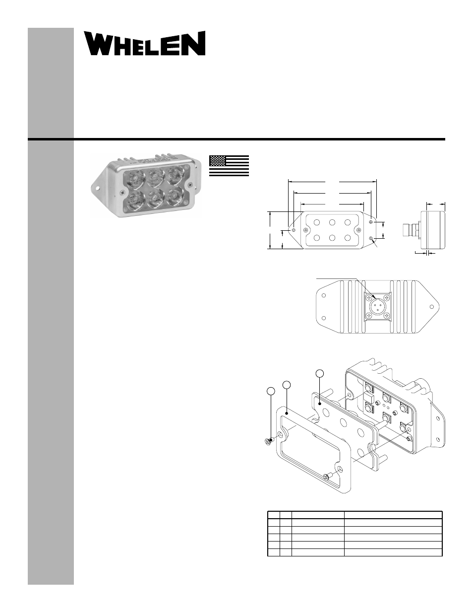
4.56
4.00
3XØ.164
.84
3.25
1.95
.975
.08
.95
1
2
3
2
3
1
ITEM
PART NUMBER
DESCRIPTION
MODEL 7112530 FINAL ASSEMBLY
4-40 X 3/8" 100° CSK PFH
BEZEL, TIR REFLECTOR 2X3 OPTIC
REFLECTOR, CLEAR OPTIC TIR 2X3 10°
0 1 - 0 7 7 11 2 5 - 3 0
1 4 - 0 0 5 0 5 8 1 - 0 4
11 - 4 7 11 3 8 - 1 0 0
6 8 - 5 9 7 11 3 6 - 0 0
QTY
1
1
2
*
POS A: +28V
POS B: GND
POS C: N/C
D38999 / 20FA98PN
Connector Orientation
®
ENGINEERING COMPANY INC.
51 Winthrop Road
Chester, Connecticut 06412-0684
Phone: (860) 526-9504
Fax: (860) 526-2009
Internet: www.whelen.com
Sales/Service e-mail: [email protected]
Aviation
Installation Guide:
Aviation model(s): 7112530
P/N: 01-0771125-30
LED Taxi Light Assembly
©2011 Whelen Engineering Company Inc.
Form No.14479 (032411)
SPECIFICATIONS:
Nominal Operational Voltage:.................. 28VDC
Input Current (Nominal): .......................... 0.45 Amps
CONTINUED AIRWORTHINESS:
The Taxi Light, Model 7112530, consists of a single
bank of six LEDs. If one LED fails as a short, the other
five will continue to operate. If an LED fails open, all six
LEDs will be off. There is no FAR requirement for this
light. Inspect the lens. replace if there is excessive
scratching, pitting, discoloration or cracking.
INSTALLATION PROCEDURES:
The following information is to assist in the installation
of a Whelen Taxi light.
1.
The installation procedure described in the
following text will be confined to a single light
installation, but is identical for multiple light
installations.
2.
Connect the Taxi light inputs according to the chart
shown. Connect the power lead to an
appropriately sized breaker. Connections to be in
accordance with FAA approved methods.
3.
Using appropriate hardware, install light assembly
and insure that all leads are clear of any
obstructions and ty-rap as required. Secure light
assembly, using vibration resistant threaded
fasteners.
4.
Check all avionics systems for interference from
this installation.
5.
A flight check should be performed by a properly
certified pilot.
6.
When necessary, waterproof the light base to
aircraft. Apply single part silicone (RTV) or
equivalent around any open area where water
could get in.
7.
Update aircraft records, complete Form 337 and
obtain FAA field approval for installation, as
necessary.
MADE IN THE U.S.A.