Whelen 7090002 User Manual
Aviation
Page 1
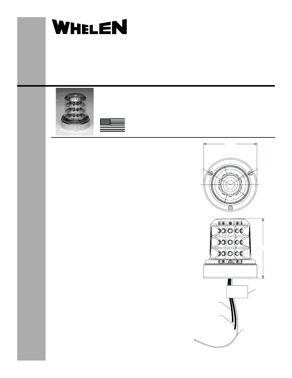
3.66
Teflon Tube 18GA
(Pressure Venting)
(-)Ground Black 18GA
Teflon Wire 18"LG
4.14±.07
MFG Label
or
(+)28VDC White 18GA
Teflon Wire 18”LG
(+)14VDC Red 18GA
Teflon Wire 18”LG
®
ENGINEERING COMPANY INC.
Route 145, Winthrop Road,
Chester, Connecticut 06412
Phone: (860) 526-9504
Fax: (860) 526-2009
Internet: www.whelen.com
Sales/Service e-mail: [email protected]
Aviation
©2003 Whelen Engineering Company Inc.
Form No.13827D (111505)
OPERATING INSTRUCTIONS:
Operational Voltage: . . . . . . . . . . . . 14 / 28 VDC nominal
Average Input Current: . . . . . . . . . . 0.85 / 0.425 Amps
Peak Input Current: . . . . . . . . . . . . . 4.5 / 2.25 Amps @ .25 Seconds
The Model 70900 series LED anti-collision light assembly meets the
requirements of FAR 91.205(c)(3).
CONTINUED AIRWORTHINESS: The 70900 series LED anti-collision light
assembly is designed with 10 vertical columns consisting of 3 LEDs each.
Should any one LED or any vertical column fail, the unit must be repaired or
replaced.
INSTALLATION PROCEDURES: The following information is to assist in
the installation of a Whelen LED Flashing Anti-collision Light System.
1.
The installation procedure described in the following text will be confined
to a single light installation, but is identical for multiple light installations.
2.
Using the “suggested mounting hole pattern” prepare the aircraft for
means to secure the LED Flashing Anti-collision Light assembly.
3.
14/28 VDC (+) and (-) ground leads equipped with an appropriate sized
breaker to be supplied to the LED Flashing Anti-collision Light Assembly
System. Both leads must be connected by an approved FAA connection.
Insure that the wire leads and the pressure venting tube are all clear of
any obstructions and ty-wrap as required. The pressure venting tube may
be trimmed to minimum length of 1” from base.
4.
Install the light assembly by first removing the lens. Remove the 3 screws
that attach the mounting adaptor plate.
5.
Install adaptor plate onto aircraft. Re-mount the unit onto the adaptor
plate and re-install lens screws with 5-7 in./lbs. of torque.
6.
Check all avionics systems for interference from this installation.
7.
A flight check should be performed by a properly certified pilot.
8.
All inverted (bottom) mounted units shall require waterproofing of the
mounting hardware. An application of single-part silicone (RTV) or
equivalent applied over top of the mounting hardware, after installation, is
recommended. Reference page 2 for an illustration. Inverted and/or
standard mounted units, when necessary, may require waterproofing
around any open area where water could get in. Specifically, the lens to
the flasher base assembly, and the flasher base assembly to the aircraft.
Note: It is permissable to drill a 1/8” hole in the center of the lens for
bottom mount units.
9.
Update aircraft records, complete Form 337 and obtain FAA field approval
for installation.
TSO-C96a CLASS III
APPROVED
MADE IN THE U.S.A.
Installation Guide:
Model 70900( )-series
Model 7090002
7090003
P/N:01-0770900-02
01-0770900-03
LED Flashing Anti-Collision
Light Assembly
The conditions and tests required for TSO approval of this
article are minimum performance standards. It is the
responsibility of those installing this article either on or
within a specific type or class of aircraft to determine that
the aircraft installation conditions are within the TSO
standards. TSO articles must have separate approval for
installation in aircraft. The article may be installed only if
performed under 14 CFR part 43 or the applicable
airworthiness requirements.