Whelen 7145700 User Manual
Aviation, Engineering company inc
Page 1
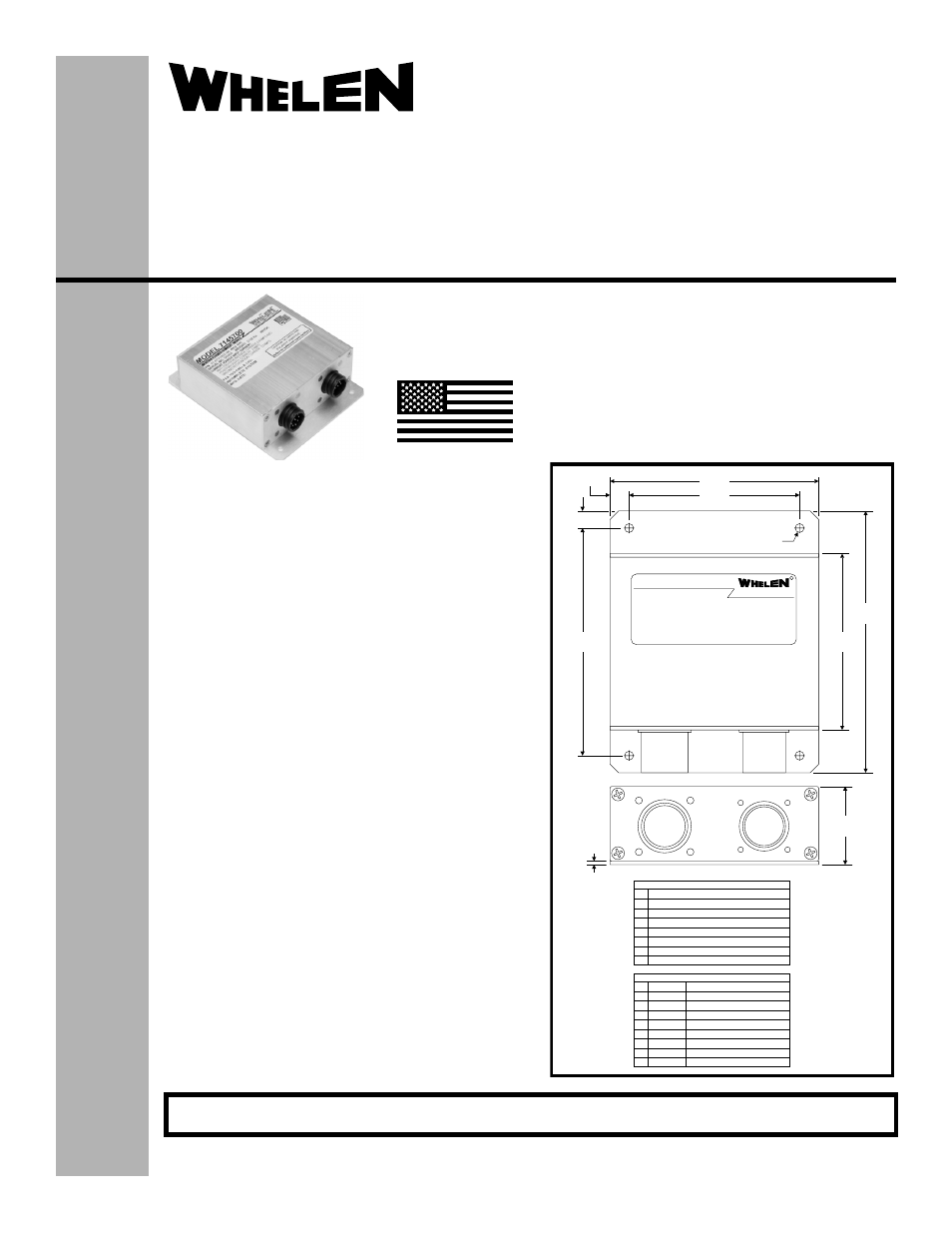
4X .Ø156
CHESTER, CONNECTICUT 06412-0684
ENGINEERING COMPANY, INC.
BY:
R
MODEL 7145700
3.67
3.00
.335
.30
4.00
3.10
4.60
J1
INPUT
J2
OUTPUT
1.38
.062
J2
J1
1 AC1
J2 CPC 206486-1
2 AC2
Anti-Collision Light
Anti-Collision Light
3 AC3
Anti-Collision Light
4 AC4
Anti-Collision Light
5 V+
V IN
6 AC5
Anti-Collision Light
9 Cathode Ground Recognition Light
7 AC6
Anti-Collision Light
8 Cathode Forward Position Light
1 +28V Anti-Collision Light
2 Ground
3 SYNC (see note)
4 +28V Position Light
5
6 No Connection
7 No Connection
8 No Connection
+28V Ground Recognition Light
J1 CPC 205841-1
Model:7145700
®
ENGINEERING COMPANY INC.
Aviation
Installation Guide:
Aviation model 7145700
P/N 01-0771457-00
Flasher/Current Source
©2010 Whelen Engineering Company Inc.
Form No.14397A (050511)
For warranty information regarding this product, visit www.whelen.com/warranty
SPECIFICATIONS:
Nominal Operational Voltage:............................................ 28 VDC
(Operation from 22-32 VDC)
Input Current (with 905690x Lighthead):
LED Forward Position Light ........................................... 0.23 Amps
LED Anti-Collision Light ([email protected] Sec.) ................... 3.9 Amps
LED Anti-Collision Light (Avg.) ...................................... 0.73 Amps
LED Ground Recognition Light ([email protected] Sec.)........ 0.5 Amps
LED Ground Recognition Light (Avg.)........................... 0.09 Amps
Flashrate.............................................................................. 45 ±5 Per. Min.
EQUIPMENT LIMITATIONS:
An approved Anti-Collision / Position Light System consists of at least 2
flasher/current source units, each connected to a LED anti-collision,
position and ground recognition light lighthead.
Per FAR 23.1401(d) or 25.1401(d), do not operate the anti-collision light
and the ground recognition light at the same time.
The Ground Recognition Light is a non-TSO function.
Certain types of installations may require additional testing.
CONTINUED AIRWORTHINESS:
If any bank of LEDs fail, the lighthead module should be checked. If the
module checks good, replace the flasher.
Note: An anti-collision light will automatically shut-off after 9-10 flashes if
a failure is detected.
INSTALLATION PROCEDURES:
1.
Consider areas or locations designated by the aircraft
manufacturer. Check that breakers are properly rated.
2.
Attach the flasher using the (4) 0.156 dia. mounting holes.
3.
Connect the inputs according to the chart shown. Connections to
be in accordance with FAA approved methods.
4.
Check all avionic systems for interference from the installation
5.
A flight check should be performed by a certified pilot
6.
Update aircraft records, complete form 337 and obtain FAA field
approval for installation, as necessary
Note: SYNC is a low power, bi-directional control signal. Connecting to
the synchronize signal of any Whelen LED anti-collision assembly will
cause the lights to flash at the same time. If syncronization is not
necessary, the connection may be left open.
MADE IN THE U.S.A.
The conditions and tests required for TSO approval of this
article are minimum performance standards. It is the
responsibility of those installing this article either on or
within a specific type or class of aircraft to determine that
the aircraft installation conditions are within the TSO
standards. TSO articles must have separate approval for
installation in aircraft. The article may be installed only if
performed under 14 CFR part 43 or the applicable
airworthiness requirements.
TSO-C30c
TYPES I, II & III /
TSO-C96a
CLASS II APPROVED
51 Winthrop Road
Chester, Connecticut 06412-0684
Phone: (860) 526-9504
Fax: (860) 526-2009
Internet: www.whelen.com
Sales/Service e-mail: [email protected]