Whelen 90192 User Manual
Aviation, Engineering company inc
Page 1
®
ENGINEERING COMPANY INC.
INPUT
PIONEERS IN SAFETY SIGNALS
ENGINEERING COMPANY, INC.
CHESTER, CONNECTICUT 06412-0684
MODEL 90192
PN: 01-0790192-XX
14VDC @ 4A 28VDC @ 2A
WEIGHT 2.1 lbs.
MFG. DATE:
SERIAL NUMBER:
Wait 5 minutes after shutting
off before starting any work on
the Strobe Light Sytem.
CAUTION: DC UNITS ARE
POLARITY SENSITIVE.
Black lead is negative.
NOTICE: DO NOT TAMPER
WITH POWER SUPPLY.
This unit is sold as a
COMPLETE MODULE, not
designed for field repair.
Return to authorized repair facilties.
WARNING
HIGH VOLTAGE
OUTPUT
Route 145, Winthrop Road,
Chester, Connecticut 06412
Phone: (860) 526-9504
Fax: (860) 526-2009
Internet: www.whelen.com
Sales/Service e-mail: [email protected]
Aviation
Installation Guide
Model 90192 - ( )
Strobe Anti-collision Power Supply
©1997 Whelen Engineering Company Inc.
Form No.13225C (091697)
TSO-C96a
APPROVED
MADE IN THE U.S.A.
90192-( ) STROBE ANTI-COLLISION POWER SUPPLY
ASSEMBLY OPERATING INSTRUCTIONS.
Nominal Operational Voltage:
14 VOLTS / 28 VOLTS
Average Input Current:
4 AMPS / 2 AMPS
Output Voltage:
550V Nominal
EQUIPMENT LIMITATIONS: Recommended minimum wire size is
20 AWG and is installation dependant to meet FAR requirements for
light output. Avoid moisture, salt or dust environment.
INSTALLATION PROCEDURES: The following information is to
assist you in installing a Whelen anti-collision light power supply.
Install in accordance with AC 43.13-1A and 2A.
1.
Choose the appropriate Model 90192-( ) replacement power
supply which is applicable to your aircraft.
2.
The installation procedure described in the following text will be
confined to a “single light” power supply, but is identical for
multiple power supply installation if required.
3.
Remove old power supply, locate and save existing +14 VDC
or+28 VDC lead and (-) ground leads. Clean and prep lead ends
as required.
4.
Use existing mounting holes and hardware.
NOTE: If a special mounting adapter plate is required, contact
Whelen Aviation Division for requirements.
5.
Connect existing +14 VDC or +28 VDC lead to the POSITIVE
(+) lead on the power supply assembly and connect existing (-)
ground lead to the NEGATIVE (-) lead on the power supply
assembly. Both leads must be connected by an approved
aircraft connection.
6.
Make sure existing system is equipped with an appropriate
sized breaker.
7.
Check all avionics systems for interference from this installation.
8.
A flight check should be performed by a properly certified pilot.
9.
Update aircraft records and complete Form 337.
10. Obtain FAA field approval for installation.
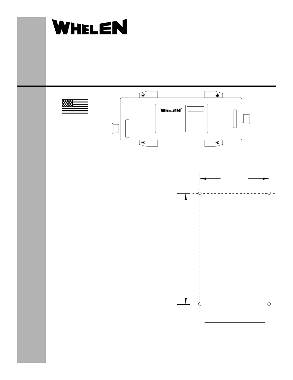
SUGGESTED MOUNTING PLAN
6.181
3.938