Whelen Vendor Field Service User Manual
Aviation, Important
Page 1
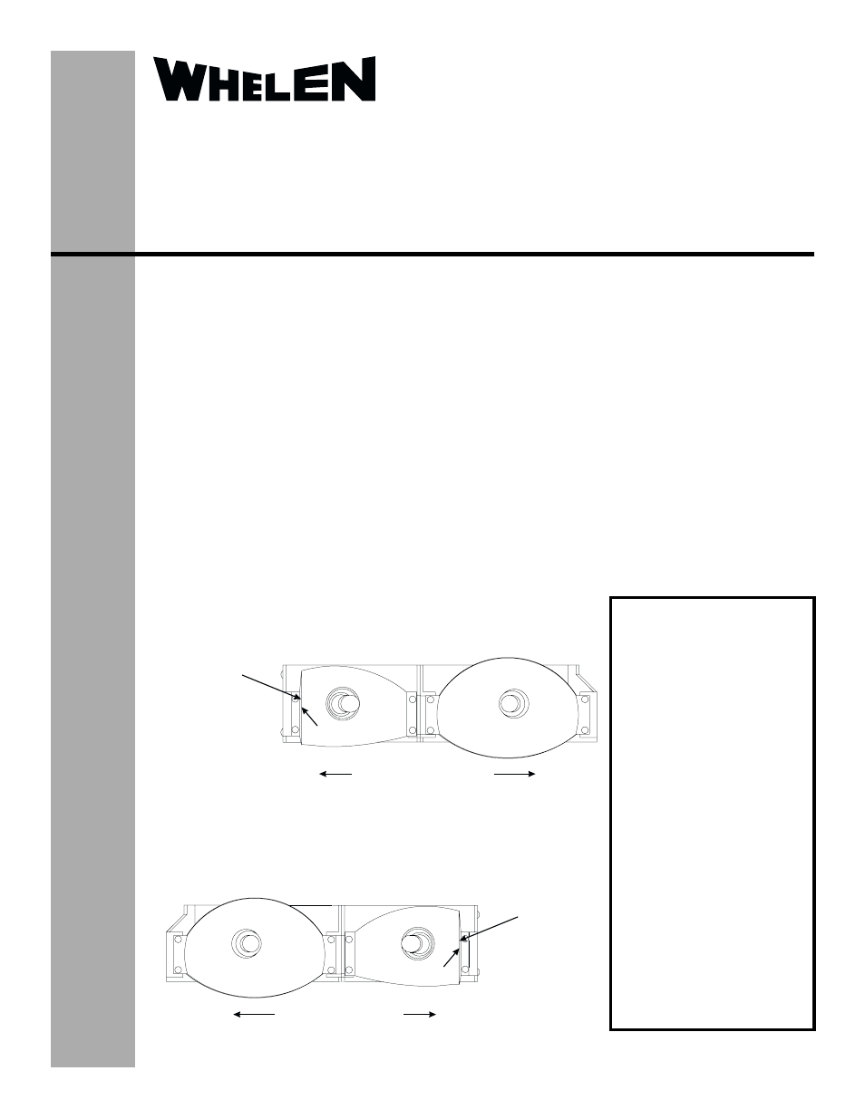
Right-side Landing/Taxi Light Assembly
(Proper Orientation Shown)
Taxi Light Assembly
Inboard
Outboard
Flat Vertical
Reflector Wall
Landing Light Assembly
Right Side
Taxi Reflector
P/N 68-5C70680-01
Taxi Light Assembly
Inboard
Outboard
Landing Light Assembly
Left Side
Taxi Reflector
P/N 68-5C70679-01
Left-side Landing/Taxi Light Assembly
(Proper Orientation Shown)
Flat Vertical
Reflector Wall
®
ENGINEERING COMPANY INC.
Route 145, Winthrop Road,
Chester, Connecticut 06412
Phone: (860) 526-9504
Fax: (860) 526-2009
Internet: www.whelen.com
Sales/Service e-mail: [email protected]
Aviation
VENDOR FIELD SERVICE BULLETIN
Effective Date: 09/05/2001
Landing/Taxi Light Assembly
P/N: 01-0790131-06 (Right-side Assembly)
P/N: 01-0790131-05 (Left-side Assembly)
©2001 Whelen Engineering Company Inc.
Form No.13624A (012201)
Important
-
The purpose of this document is to identify and repair improperly oriented taxi light reflectors that
may be present in some Landing/Taxi light assemblies. The suspect assemblies were manufactured between 01/02/
01 and 08/29/01. The manufactured date code is located on the outboard vertical end of the landing/taxi light
assembly (see following page). NOTE: If inspection of aircraft reveals improperly oriented taxi reflectors with
date codes outside the specified date code range, contact Whelen Engineering. If visual inspection determines
that either or both taxi light reflectors are improperly oriented, follow the instructions in this manual regarding
replacement and re-installation procedures. The taxi light reflectors MAY NOT be rotated 180° within the assembly
to gain proper orientation.
Access to the light assembly in question may be gained in two ways and is at the operator’s discretion: (1) Removal
of the light assembly’s outer glass lens for reflector removal without removing the complete assembly or, (2) removal
of the access panel located under the wing beneath the light assembly and complete removal of the entire assembly.
This document assumes the light assembly has been removed for this procedure.
Please note that the terms “Left” or “Right” are referenced from the pilot’s seated position, while “Inboard” and
“Outboard” are relative to the mounted Landing/Taxi light assembly as it relates to the centerline of the plane.
Beginning with the Landing/Taxi light assembly mounted on the Left wing, visually inspect the inboard (Taxi)
reflector. Note that this reflector should be oriented as shown, with the flat vertical reflector wall located in the
inboard position.
When inspection of the left Landing/Taxi light assembly is completed,
proceed to the right Landing/Taxi light assembly. As shown, the flat vertical
reflector wall should be oriented so that it is in the inboard position.
Attention!
If both the left and right
light assemblies are
improperly oriented, the
taxi reflectors may be
removed from their
present location and
installed on the opposite
wing’s light assembly. In
these cases, no
additional reflectors will
be needed.
If a single light assembly
is improperly oriented,
the correct reflector must
be installed and the
original reflector returned
to:
Whelen Engineering
attn: Aviation Sales Dept.