Whelen 7106502 User Manual
Aviation
Page 1
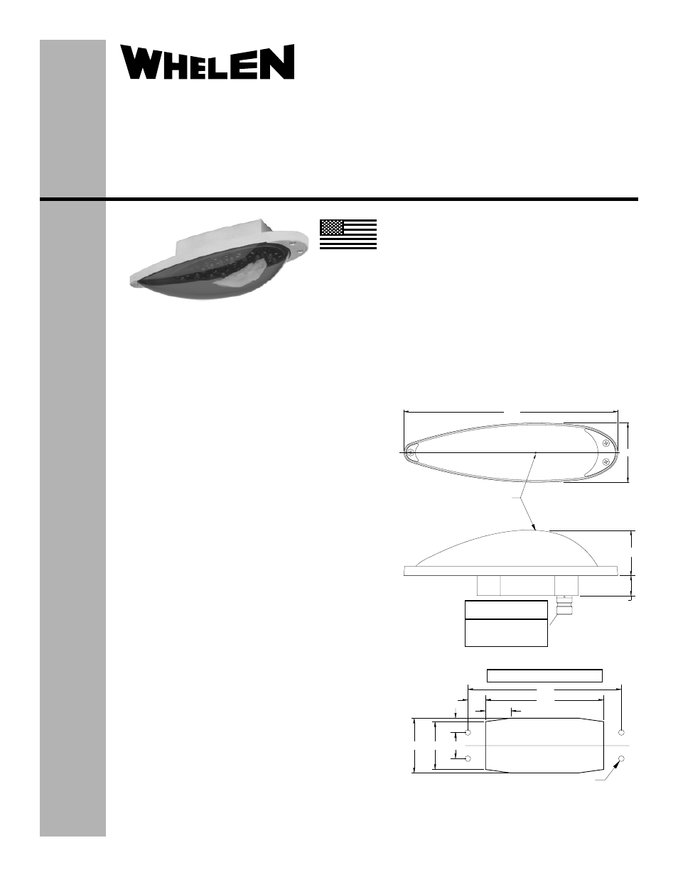
5.46
4.20
.63
.51
.936
SUGGESTED MOUNTING PLAN
1.70
1.95
.90 TYP
.80
CLEARANCE FOR #10-32
HARDWARE TYP 4 PLACES
CONNECTOR WIRING
JD38999 / 20FA98PN
POS. A
POS. B
POS. C
(+) 28VDC
( - ) GROUND
(N/C)
1.81
DRAIN
HOLE
2.38
8.57
®
ENGINEERING COMPANY INC.
51 Winthrop Road
Chester, Connecticut 06412-0684
Phone: (860) 526-9504
Fax: (860) 526-2009
Internet: www.whelen.com
Sales/Service e-mail: [email protected]
Aviation
Installation Guide:
Aviation model: 7106502
P/N: 01-0771065-02
LED Ground Recognition Light Assembly
©2011 Whelen Engineering Company Inc.
Form No.14478 (032411)
SPECIFICATIONS:
Nominal Operational Voltage:.................. 28VDC
Input Current:............................................ 0.53 Amps
Pulse @ 0.2 Sec.:...................................... 2.0 Amps
Flashrate: .................................................. 80± 10% per min.
EQUIPMENT LIMITATIONS:
The baseplate must be mounted parallel to the vertical and
horizontal centerlines of the aircraft to project the patterns
properly.
CONTINUED AIRWORTHINESS:
The Ground Recognition Light, Model 7106502, consists of
two banks of eight LEDs, for a total of 16 LEDs. If one LED
fails as a short, the other 15 will continue to operate. If an
LED fails open, all eight LEDs in that bank will be off, the
other bank will operate normally. There is no FAR
requirement for this light. Inspect the lens. Replace if there
is excessive scratching, pitting, discoloration or cracking.
INSTALLATION PROCEDURES:
The following information is to assist in the installation of a
Whelen Ground Recognition Light.
1.
Using the mounting detail information provided,
prepare the aircraft for means to secure the LED light
assembly.
2.
Connect the light inputs according to the chart shown.
Connect the power lead to an appropriate sized
breaker. Connections to be in accordance with FAA
approved methods.
3.
Remove the lens retainers and lens from the assembly
CAUTION! Do not touch the LED lens surface with
either fingers or sharp objects. This could soil and/or
damage the lens and effect the optical performance of
the LED.
4.
Using appropriate hardware, install light assembly and
insure that all leads are clear of any obstructions and
secured as required. Secure light assembly using
vibration resistant threaded fasteners.
5.
Reinstall the lens. Confirm proper gasket fit.
6.
Install lens retainers. Re-insert #6 flat head screws
and tighten firmly.
7.
When necessary, waterproof the light base to
aircraft. Apply single part silicone (RTV) or
equivalent around any open area where water could
get in, with the exception of the drain hole.
8.
Check all avionics systems for interference from the
installation.
9.
A flight check should be performed by a properly
certified pilot.
10. Update aircraft records, complete Form 337 and
obtain FAA field approval for installation, as
necessary.
MADE IN THE U.S.A.
- 9045000 9036801 9036802 7108008 7108018 9056905 9056906 7155404 7155405 7155406 90340 series 7105500 7123404 7112000 7123402 7114800 7114801 OR6502GE OR6502RE 7118400 7118401 7108040 7117001 7117002 7117007 7117008 7117009 7117010 7108019 9027701 9027702 7105000 7105001 7105010 7105011 9052008 9052018 7145751